Cirkit Designer Logo
Cirkit Designer
Your all-in-one circuit design IDE
Home / 
Component Documentation

How to Use Adafruit PCT2075: Examples, Pinouts, and Specs

Image of Adafruit PCT2075
Cirkit Designer LogoDesign with Adafruit PCT2075 in Cirkit Designer

Introduction

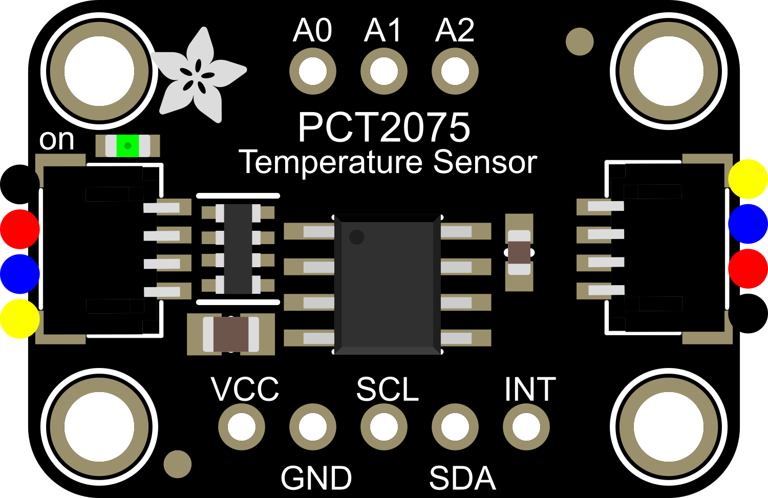
The Adafruit PCT2075 is a digital temperature sensor module that offers high-accuracy temperature measurements using I2C communication. This sensor is based on the PCT2075 temperature sensor IC and is designed for easy integration into a wide range of electronic projects, including environmental monitoring, system temperature feedback, and IoT applications.

Explore Projects Built with Adafruit PCT2075

Use Cirkit Designer to design, explore, and prototype these projects online. Some projects support real-time simulation. Click "Open Project" to start designing instantly!
Battery-Powered Smart Light with Proximity Sensor and OLED Display using Adafruit QT Py RP2040
Image of lab: A project utilizing Adafruit PCT2075 in a practical application
This circuit is a portable, battery-powered system featuring an Adafruit QT Py RP2040 microcontroller that interfaces with an OLED display, a proximity sensor, an accelerometer, and an RGB LED strip. The system is powered by a lithium-ion battery with a step-up boost converter to provide 5V for the LED strip, and it includes a toggle switch for power control. The microcontroller communicates with the sensors and display via I2C.
Cirkit Designer LogoOpen Project in Cirkit Designer
Battery-Powered Smart Sensor Hub with Adafruit QT Py RP2040
Image of wearable final: A project utilizing Adafruit PCT2075 in a practical application
This circuit features an Adafruit QT Py RP2040 microcontroller interfaced with an APDS9960 proximity sensor, an MPU6050 accelerometer and gyroscope, and an OLED display via I2C communication. It also includes a buzzer controlled by the microcontroller and is powered by a 3.7V LiPo battery with a toggle switch for power control.
Cirkit Designer LogoOpen Project in Cirkit Designer
Battery-Powered Sensor Hub with Adafruit QT Py RP2040 and OLED Display
Image of 512: A project utilizing Adafruit PCT2075 in a practical application
This circuit features an Adafruit QT Py RP2040 microcontroller interfacing with an MPU-6050 accelerometer, an Adafruit APDS-9960 sensor, and a 0.96" OLED display via I2C communication. It is powered by a 3.7V LiPo battery and includes a green LED with a current-limiting resistor connected to an analog pin of the microcontroller.
Cirkit Designer LogoOpen Project in Cirkit Designer
Battery-Powered Arduino UNO Smart Light with NeoPixel and ADXL345
Image of Cubagick: A project utilizing Adafruit PCT2075 in a practical application
This circuit is a battery-powered system featuring an Arduino UNO that controls an Adafruit NeoPixel Stick and interfaces with an ADXL345 accelerometer and an ILI9341 TFT display. The TP4056 module charges a 18650 battery, which powers the system through a DC-DC converter. The Arduino code drives the NeoPixel Stick to display a red light sequence.
Cirkit Designer LogoOpen Project in Cirkit Designer

Explore Projects Built with Adafruit PCT2075

Use Cirkit Designer to design, explore, and prototype these projects online. Some projects support real-time simulation. Click "Open Project" to start designing instantly!
Image of lab: A project utilizing Adafruit PCT2075 in a practical application
Battery-Powered Smart Light with Proximity Sensor and OLED Display using Adafruit QT Py RP2040
This circuit is a portable, battery-powered system featuring an Adafruit QT Py RP2040 microcontroller that interfaces with an OLED display, a proximity sensor, an accelerometer, and an RGB LED strip. The system is powered by a lithium-ion battery with a step-up boost converter to provide 5V for the LED strip, and it includes a toggle switch for power control. The microcontroller communicates with the sensors and display via I2C.
Cirkit Designer LogoOpen Project in Cirkit Designer
Image of wearable final: A project utilizing Adafruit PCT2075 in a practical application
Battery-Powered Smart Sensor Hub with Adafruit QT Py RP2040
This circuit features an Adafruit QT Py RP2040 microcontroller interfaced with an APDS9960 proximity sensor, an MPU6050 accelerometer and gyroscope, and an OLED display via I2C communication. It also includes a buzzer controlled by the microcontroller and is powered by a 3.7V LiPo battery with a toggle switch for power control.
Cirkit Designer LogoOpen Project in Cirkit Designer
Image of 512: A project utilizing Adafruit PCT2075 in a practical application
Battery-Powered Sensor Hub with Adafruit QT Py RP2040 and OLED Display
This circuit features an Adafruit QT Py RP2040 microcontroller interfacing with an MPU-6050 accelerometer, an Adafruit APDS-9960 sensor, and a 0.96" OLED display via I2C communication. It is powered by a 3.7V LiPo battery and includes a green LED with a current-limiting resistor connected to an analog pin of the microcontroller.
Cirkit Designer LogoOpen Project in Cirkit Designer
Image of Cubagick: A project utilizing Adafruit PCT2075 in a practical application
Battery-Powered Arduino UNO Smart Light with NeoPixel and ADXL345
This circuit is a battery-powered system featuring an Arduino UNO that controls an Adafruit NeoPixel Stick and interfaces with an ADXL345 accelerometer and an ILI9341 TFT display. The TP4056 module charges a 18650 battery, which powers the system through a DC-DC converter. The Arduino code drives the NeoPixel Stick to display a red light sequence.
Cirkit Designer LogoOpen Project in Cirkit Designer

Technical Specifications

Key Technical Details

  • Supply Voltage: 2.7V to 5.5V
  • Temperature Range: -40°C to +125°C
  • Accuracy: ±1°C (from -25°C to +100°C)
  • Resolution: 0.1°C
  • Interface: I2C
  • I2C Address: Configurable, default 0x28 (up to 8 addresses selectable)
  • Operating Current: 1 mA (typical)

Pin Configuration and Descriptions

Pin Number Pin Name Description
1 VDD Power supply (2.7V to 5.5V)
2 SDA I2C Data line
3 SCL I2C Clock line
4 OS Over-temperature Shutdown output (active low)
5 GND Ground

Usage Instructions

Integration into a Circuit

  1. Power Supply: Connect the VDD pin to a 2.7V to 5.5V power source and the GND pin to the ground.
  2. I2C Communication: Connect the SDA and SCL pins to the I2C data and clock lines, respectively. Ensure pull-up resistors are in place if they are not provided by the microcontroller board.
  3. Over-temperature Shutdown: The OS pin can be connected to an interrupt pin on a microcontroller to trigger an action when a set temperature threshold is exceeded.

Best Practices

  • Use decoupling capacitors close to the sensor's power supply pins to filter out noise.
  • Avoid placing the sensor near heat-generating components to prevent false readings.
  • Ensure that the I2C bus has appropriate pull-up resistors, typically 4.7kΩ to 10kΩ.

Example Code for Arduino UNO

#include <Wire.h>

// PCT2075 I2C address (default)
#define PCT2075_ADDRESS 0x28

// Register addresses
#define TEMP_REGISTER 0x00

void setup() {
  Wire.begin(); // Initialize I2C
  Serial.begin(9600); // Start serial communication
}

void loop() {
  Wire.beginTransmission(PCT2075_ADDRESS);
  Wire.write(TEMP_REGISTER); // Point to the temperature register
  Wire.endTransmission();

  Wire.requestFrom(PCT2075_ADDRESS, 2); // Request 2 bytes from the sensor
  if (Wire.available() == 2) {
    int tempRaw = Wire.read() << 8 | Wire.read(); // Read the temperature value
    float temperature = tempRaw / 256.0; // Convert to Celsius
    Serial.print("Temperature: ");
    Serial.print(temperature);
    Serial.println(" C");
  }

  delay(1000); // Wait for 1 second before reading again
}

Troubleshooting and FAQs

Common Issues

  • Inaccurate Temperature Readings: Ensure the sensor is not placed near heat sources and that the I2C bus is free from noise.
  • No Communication: Check the wiring, ensure correct pull-up resistors are in place, and verify that the sensor's power supply is within the specified range.

Solutions and Tips

  • Noise Reduction: Use shielded cables for I2C lines and keep the sensor away from high-frequency signals.
  • Address Conflict: Make sure no other device on the I2C bus has the same address as the PCT2075.

FAQs

Q: Can I change the I2C address of the sensor? A: Yes, the PCT2075 has configurable I2C addresses. Refer to the datasheet for instructions on setting a different address.

Q: What is the maximum distance for the I2C bus? A: I2C is typically used for short distances, but with proper bus buffering and lower speeds, it can be extended. Keep the lines as short as possible for reliable communication.

Q: How do I calibrate the sensor? A: The PCT2075 is factory-calibrated. However, if you need to adjust the readings, this should be done in software by applying an offset.

Q: Is the sensor waterproof? A: No, the Adafruit PCT2075 is not waterproof. Protect it from moisture and liquids to ensure proper operation.