
How to Use 5A Fuse: Examples, Pinouts, and Specs
 Design with 5A Fuse in Cirkit Designer
Introduction
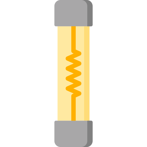
A 5A fuse is a safety device designed to protect electrical circuits by interrupting the flow of current when it exceeds 5 amperes. This prevents damage to sensitive components, reduces the risk of overheating, and minimizes the chance of electrical fires. Fuses are essential in both household and industrial applications, ensuring the safety and longevity of electrical systems.
Explore Projects Built with 5A Fuse
 Open Project in Cirkit Designer
 Open Project in Cirkit Designer
 Open Project in Cirkit Designer
 Open Project in Cirkit Designer
Explore Projects Built with 5A Fuse
Open Project in Cirkit DesignerOpen Project in Cirkit DesignerOpen Project in Cirkit DesignerOpen Project in Cirkit DesignerCommon Applications and Use Cases
- Protection of household appliances such as fans, lights, and small kitchen devices.
- Automotive circuits to safeguard wiring and components.
- Industrial equipment to prevent overcurrent damage.
- Power supplies and battery-operated devices for circuit protection.
Technical Specifications
The following table outlines the key technical details of a standard 5A fuse:
| Parameter | Specification |
|---|---|
| Rated Current | 5 Amperes |
| Rated Voltage | Typically 250V AC or 32V DC |
| Breaking Capacity | Varies (e.g., 35A, 100A, or higher) |
| Fuse Type | Fast-blow (F) or Slow-blow (T) |
| Material | Glass or ceramic body with metal caps |
| Operating Temperature | -55°C to +125°C |
| Dimensions | Common sizes: 5x20mm, 6.3x32mm |
Pin Configuration and Descriptions
A fuse does not have traditional pins like ICs or transistors. Instead, it has two terminals (metal caps) for connection. These terminals are typically inserted into a fuse holder or soldered directly into a circuit.
| Terminal | Description |
|---|---|
| Terminal 1 | Input terminal for current flow |
| Terminal 2 | Output terminal for current flow |
Usage Instructions
How to Use the 5A Fuse in a Circuit
- Determine the Current Rating: Ensure the 5A fuse is appropriate for your circuit. The fuse rating should be slightly higher than the normal operating current but lower than the maximum current the circuit can handle.
- Select the Fuse Type: Choose between fast-blow (F) or slow-blow (T) fuses based on the application:
- Use fast-blow fuses for sensitive electronics that require immediate protection.
- Use slow-blow fuses for circuits with inrush currents, such as motors or transformers.
- Install the Fuse:
- Insert the fuse into a compatible fuse holder or clip.
- Ensure the fuse is securely connected to avoid loose contacts.
- Test the Circuit: Power on the circuit and verify that the fuse operates correctly under normal conditions.
Important Considerations and Best Practices
- Voltage Rating: Always use a fuse with a voltage rating equal to or greater than the circuit voltage.
- Replacement: Replace a blown fuse with one of the same type and rating to maintain proper protection.
- Environment: Avoid exposing the fuse to excessive heat, moisture, or vibration, as these can affect its performance.
- Safety: Disconnect power before replacing or inspecting a fuse to prevent electric shock.
Example: Using a 5A Fuse with an Arduino UNO
When connecting an Arduino UNO to a power supply, a 5A fuse can be used to protect the board and connected components from overcurrent. Below is an example circuit:
- Connect the positive terminal of the power supply to one terminal of the 5A fuse.
- Connect the other terminal of the fuse to the VIN pin of the Arduino UNO.
- Connect the negative terminal of the power supply to the GND pin of the Arduino UNO.
// Example Arduino code to demonstrate a simple LED circuit
// Ensure the 5A fuse is installed between the power supply and Arduino VIN pin

int ledPin = 13; // Pin connected to the LED

void setup() {
  pinMode(ledPin, OUTPUT); // Set the LED pin as an output
}

void loop() {
  digitalWrite(ledPin, HIGH); // Turn the LED on
  delay(1000);                // Wait for 1 second
  digitalWrite(ledPin, LOW);  // Turn the LED off
  delay(1000);                // Wait for 1 second
}
Troubleshooting and FAQs
Common Issues
Fuse Blows Frequently:
- Cause: The circuit may be drawing more than 5A due to a fault or incorrect design.
- Solution: Check the circuit for short circuits or excessive loads. Verify that the fuse rating is appropriate for the application.
Fuse Does Not Blow When Expected:
- Cause: The fuse may have a higher current rating than required or may be defective.
- Solution: Replace the fuse with one of the correct rating and verify its functionality.
Loose Connections:
- Cause: The fuse is not securely installed in the holder.
- Solution: Ensure the fuse is properly seated and the holder is in good condition.
FAQs
Q: Can I use a 5A fuse in place of a 3A fuse?
A: No, using a 5A fuse in place of a 3A fuse may compromise circuit protection. Always use a fuse with the correct rating.
Q: How do I know if a fuse is blown?
A: Inspect the fuse visually. For glass fuses, look for a broken filament or discoloration. For ceramic fuses, use a multimeter to check continuity.
Q: Can I bypass a fuse temporarily?
A: Bypassing a fuse is not recommended, as it removes the circuit's protection and increases the risk of damage or fire.
Q: What is the difference between fast-blow and slow-blow fuses?
A: Fast-blow fuses respond quickly to overcurrent, while slow-blow fuses tolerate short-duration surges before blowing. Choose based on your circuit's requirements.