Cirkit Designer Logo
Cirkit Designer
Your all-in-one circuit design IDE
Home / 
Component Documentation

How to Use Soil Sensor HW-080 Connector: Examples, Pinouts, and Specs

Image of Soil Sensor HW-080 Connector
Cirkit Designer LogoDesign with Soil Sensor HW-080 Connector in Cirkit Designer

Introduction

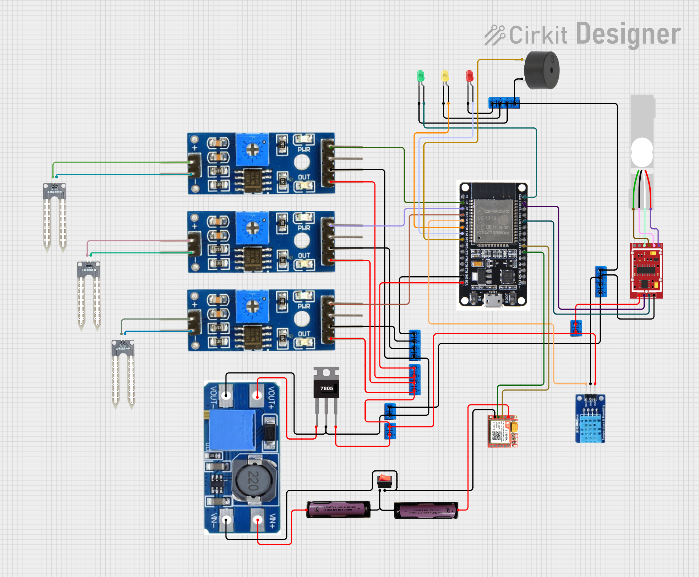
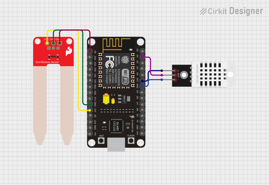
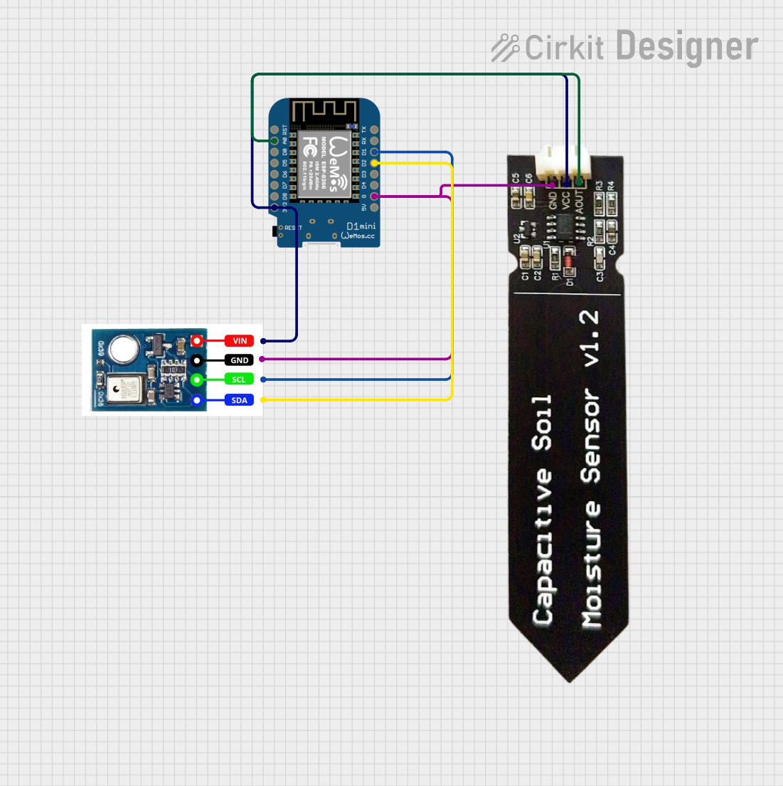
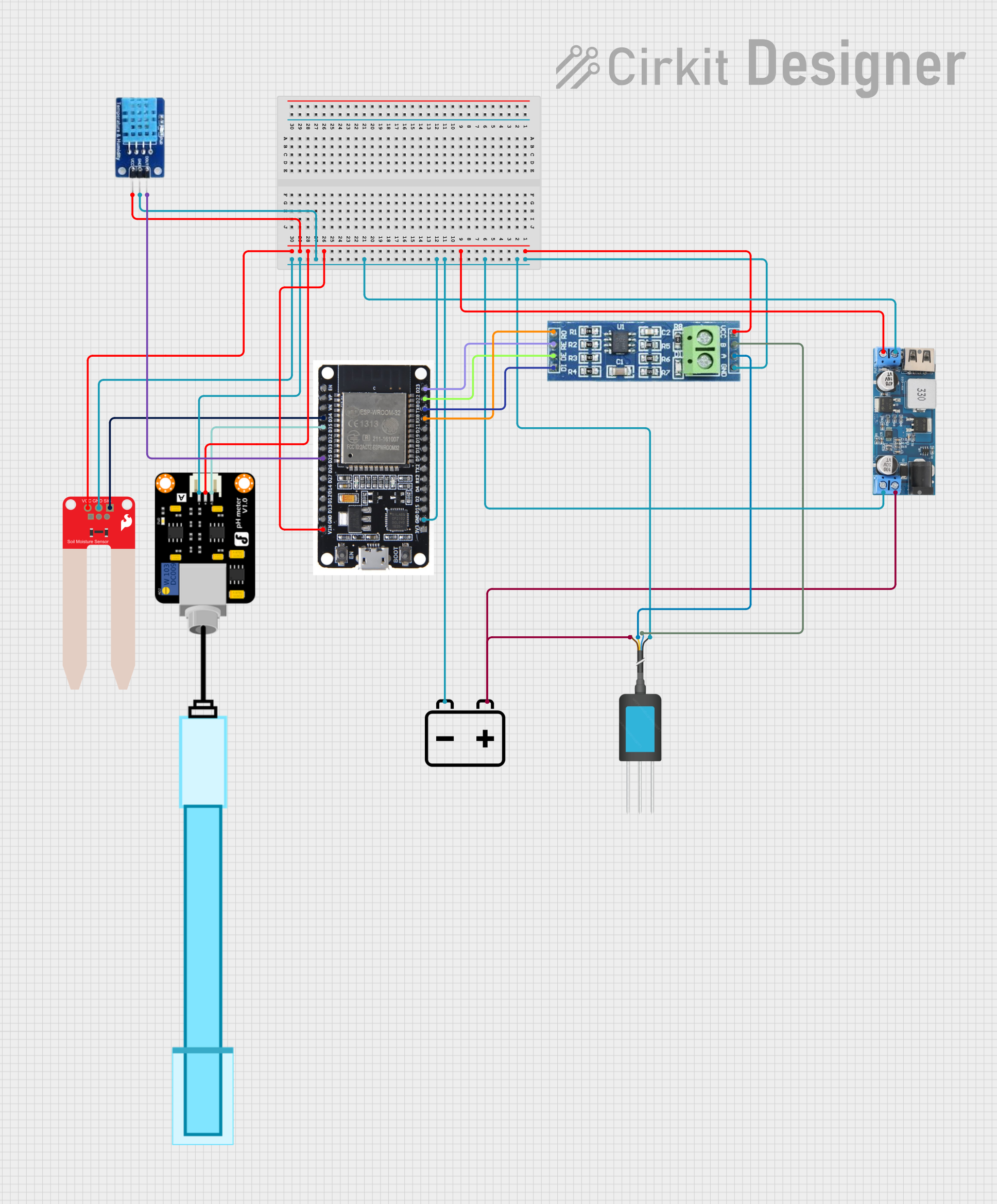
The Soil Sensor HW-080 Connector is a soil moisture sensor designed to measure the volumetric water content in soil. It provides an analog or digital output that corresponds to the moisture level, making it an essential tool for monitoring soil health. This sensor is widely used in agricultural applications, gardening, and automated irrigation systems to optimize water usage and ensure plant health.

Explore Projects Built with Soil Sensor HW-080 Connector

Use Cirkit Designer to design, explore, and prototype these projects online. Some projects support real-time simulation. Click "Open Project" to start designing instantly!
ESP32-Based Landslide Monitoring System with SMS Alerts
Image of ckt 1: A project utilizing Soil Sensor HW-080 Connector in a practical application
This circuit is designed as a landslide monitoring system that measures soil moisture, temperature, humidity, and pressure. It uses an ESP32 microcontroller to read data from soil moisture sensors, a DHT11 temperature and humidity sensor, and a HX711 load cell interface with a connected load cell for pressure measurement. The system can trigger alerts through LEDs and a buzzer, and it communicates via a SIM800L module to send SMS alerts based on the sensor thresholds.
Cirkit Designer LogoOpen Project in Cirkit Designer
ESP8266 NodeMCU Based Environmental Monitoring System
Image of Image1: A project utilizing Soil Sensor HW-080 Connector in a practical application
This circuit features an ESP8266 NodeMCU microcontroller connected to a DHT22 temperature and humidity sensor and a SparkFun Soil Moisture Sensor. The DHT22 sensor's data output is connected to the D1 pin of the NodeMCU, while the soil moisture sensor's signal is connected to the A0 analog pin. Both sensors are powered by the 3V3 output of the NodeMCU, and their grounds are connected to the NodeMCU's ground, enabling the microcontroller to monitor environmental conditions and soil moisture levels.
Cirkit Designer LogoOpen Project in Cirkit Designer
Wemos D1 Mini Based Soil Moisture and Temperature Monitoring System
Image of pfe2: A project utilizing Soil Sensor HW-080 Connector in a practical application
This circuit features a Wemos D1 Mini microcontroller connected to an AHT10 temperature and humidity sensor and a capacitive soil moisture sensor. The AHT10 communicates with the Wemos D1 Mini via I2C (with SDA connected to D2 and SCL to D1), while the soil moisture sensor's analog output is connected to the A0 pin of the Wemos D1 Mini. Both sensors and the microcontroller share a common power supply, with the 3V3 pin of the Wemos D1 Mini providing power to the sensors.
Cirkit Designer LogoOpen Project in Cirkit Designer
ESP32-Based Smart Agriculture System with Soil Moisture, Temperature, Humidity, and pH Monitoring
Image of project1: A project utilizing Soil Sensor HW-080 Connector in a practical application
This circuit is designed for environmental monitoring, featuring sensors for soil moisture (SparkFun Soil Moisture Sensor), air temperature and humidity (DHT11), water pH levels (PH Meter), and soil nutrients (NPK Soil Sensor). The ESP32 microcontroller is used to read data from these sensors. Power management is handled by a 12v to 5v step-down converter, which powers the sensors and the ESP32, and an RS485 transceiver is included for serial communication, likely for remote data transmission.
Cirkit Designer LogoOpen Project in Cirkit Designer

Explore Projects Built with Soil Sensor HW-080 Connector

Use Cirkit Designer to design, explore, and prototype these projects online. Some projects support real-time simulation. Click "Open Project" to start designing instantly!
Image of ckt 1: A project utilizing Soil Sensor HW-080 Connector in a practical application
ESP32-Based Landslide Monitoring System with SMS Alerts
This circuit is designed as a landslide monitoring system that measures soil moisture, temperature, humidity, and pressure. It uses an ESP32 microcontroller to read data from soil moisture sensors, a DHT11 temperature and humidity sensor, and a HX711 load cell interface with a connected load cell for pressure measurement. The system can trigger alerts through LEDs and a buzzer, and it communicates via a SIM800L module to send SMS alerts based on the sensor thresholds.
Cirkit Designer LogoOpen Project in Cirkit Designer
Image of Image1: A project utilizing Soil Sensor HW-080 Connector in a practical application
ESP8266 NodeMCU Based Environmental Monitoring System
This circuit features an ESP8266 NodeMCU microcontroller connected to a DHT22 temperature and humidity sensor and a SparkFun Soil Moisture Sensor. The DHT22 sensor's data output is connected to the D1 pin of the NodeMCU, while the soil moisture sensor's signal is connected to the A0 analog pin. Both sensors are powered by the 3V3 output of the NodeMCU, and their grounds are connected to the NodeMCU's ground, enabling the microcontroller to monitor environmental conditions and soil moisture levels.
Cirkit Designer LogoOpen Project in Cirkit Designer
Image of pfe2: A project utilizing Soil Sensor HW-080 Connector in a practical application
Wemos D1 Mini Based Soil Moisture and Temperature Monitoring System
This circuit features a Wemos D1 Mini microcontroller connected to an AHT10 temperature and humidity sensor and a capacitive soil moisture sensor. The AHT10 communicates with the Wemos D1 Mini via I2C (with SDA connected to D2 and SCL to D1), while the soil moisture sensor's analog output is connected to the A0 pin of the Wemos D1 Mini. Both sensors and the microcontroller share a common power supply, with the 3V3 pin of the Wemos D1 Mini providing power to the sensors.
Cirkit Designer LogoOpen Project in Cirkit Designer
Image of project1: A project utilizing Soil Sensor HW-080 Connector in a practical application
ESP32-Based Smart Agriculture System with Soil Moisture, Temperature, Humidity, and pH Monitoring
This circuit is designed for environmental monitoring, featuring sensors for soil moisture (SparkFun Soil Moisture Sensor), air temperature and humidity (DHT11), water pH levels (PH Meter), and soil nutrients (NPK Soil Sensor). The ESP32 microcontroller is used to read data from these sensors. Power management is handled by a 12v to 5v step-down converter, which powers the sensors and the ESP32, and an RS485 transceiver is included for serial communication, likely for remote data transmission.
Cirkit Designer LogoOpen Project in Cirkit Designer

Common Applications and Use Cases

  • Automated irrigation systems for agriculture and gardening
  • Soil moisture monitoring in greenhouses
  • Environmental monitoring and research
  • Smart gardening projects
  • Educational projects involving Arduino or other microcontrollers

Technical Specifications

The Soil Sensor HW-080 Connector consists of two main parts: the sensor probe and the control board. Below are the key technical details:

General Specifications

  • Operating Voltage: 3.3V to 5V
  • Output Types: Analog and Digital
  • Current Consumption: < 20mA
  • Dimensions:
    • Sensor Probe: 60mm x 20mm
    • Control Board: 30mm x 15mm
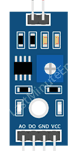
  • Interface: 4-pin connector (VCC, GND, A0, D0)
  • Moisture Range: 0% (dry) to 100% (fully wet)

Pin Configuration and Descriptions

The HW-080 Connector has a 4-pin interface. Below is the pin configuration:

Pin Name Description
1 VCC Power supply pin. Connect to 3.3V or 5V.
2 GND Ground pin. Connect to the ground of the power source.
3 A0 Analog output pin. Provides a voltage proportional to the soil moisture level.
4 D0 Digital output pin. Outputs HIGH or LOW based on the adjustable threshold.

Adjustable Threshold

The control board includes a potentiometer to adjust the threshold for the digital output (D0). This allows users to set a specific moisture level at which the digital output switches between HIGH and LOW.

Usage Instructions

How to Use the Soil Sensor HW-080 Connector in a Circuit

  1. Connect the Sensor:

    • Connect the VCC pin to a 3.3V or 5V power source.
    • Connect the GND pin to the ground of the power source.
    • Connect the A0 pin to an analog input pin on your microcontroller (e.g., Arduino).
    • Optionally, connect the D0 pin to a digital input pin if you want to use the threshold-based output.
  2. Adjust the Threshold:

    • Use a small screwdriver to turn the potentiometer on the control board.
    • Turning clockwise increases the threshold, while turning counterclockwise decreases it.
  3. Read the Output:

    • For analog readings, use the A0 pin to measure the voltage corresponding to the soil moisture level.
    • For digital readings, monitor the D0 pin to check if the soil moisture is above or below the set threshold.

Important Considerations and Best Practices

  • Avoid prolonged exposure of the sensor probe to water, as it may corrode over time.
  • Use the sensor in well-drained soil to prevent waterlogging, which can damage the probe.
  • Calibrate the sensor for your specific soil type to improve accuracy.
  • If using the sensor outdoors, consider waterproofing the control board to protect it from environmental damage.

Example Code for Arduino UNO

Below is an example code to read both analog and digital outputs from the Soil Sensor HW-080 Connector:

// Define pin connections
const int analogPin = A0; // Analog output pin connected to A0 on Arduino
const int digitalPin = 2; // Digital output pin connected to pin 2 on Arduino

void setup() {
  Serial.begin(9600); // Initialize serial communication at 9600 baud
  pinMode(digitalPin, INPUT); // Set digital pin as input
}

void loop() {
  // Read analog value from the sensor
  int analogValue = analogRead(analogPin);
  
  // Read digital value from the sensor
  int digitalValue = digitalRead(digitalPin);
  
  // Print the analog value (moisture level)
  Serial.print("Analog Value (Moisture Level): ");
  Serial.println(analogValue);
  
  // Print the digital value (threshold status)
  Serial.print("Digital Value (Threshold Status): ");
  if (digitalValue == HIGH) {
    Serial.println("Dry");
  } else {
    Serial.println("Wet");
  }
  
  delay(1000); // Wait for 1 second before the next reading
}

Troubleshooting and FAQs

Common Issues and Solutions

  1. No Output from the Sensor:

    • Ensure the sensor is properly connected to the power supply and ground.
    • Verify that the VCC pin is receiving 3.3V or 5V.
  2. Inaccurate Readings:

    • Check for corrosion on the sensor probe and clean it if necessary.
    • Calibrate the sensor for your specific soil type by comparing its readings with a known moisture level.
  3. Digital Output Always HIGH or LOW:

    • Adjust the potentiometer to set an appropriate threshold for your soil conditions.
    • Ensure the D0 pin is correctly connected to the microcontroller.
  4. Sensor Probe Corrosion:

    • Avoid leaving the probe in waterlogged soil for extended periods.
    • Consider using a corrosion-resistant coating on the probe for long-term use.

FAQs

Q: Can the sensor be used with a 3.3V microcontroller like ESP8266 or ESP32?
A: Yes, the sensor is compatible with 3.3V microcontrollers. Ensure the VCC pin is connected to a 3.3V power source.

Q: How do I waterproof the control board?
A: You can use a waterproof enclosure or apply a conformal coating to protect the control board from moisture.

Q: What is the lifespan of the sensor probe?
A: The lifespan depends on usage and environmental conditions. Regular cleaning and avoiding prolonged exposure to water can extend its life.

Q: Can I use multiple sensors in the same project?
A: Yes, you can connect multiple sensors to different analog or digital pins on your microcontroller. Ensure each sensor has a unique connection.