
How to Use NRF24 Adapter: Examples, Pinouts, and Specs
 Design with NRF24 Adapter in Cirkit Designer
Introduction
The NRF24 Adapter is a wireless transceiver module designed for short-range communication in the 2.4 GHz ISM band. Manufactured by NRF24, this module is widely used in applications such as remote controls, wireless sensors, and IoT devices. Its compact design and low power consumption make it an ideal choice for projects requiring reliable wireless communication.
The adapter simplifies the integration of the NRF24L01 transceiver module with microcontrollers, providing an easy-to-use interface for seamless communication. It is commonly used in hobbyist projects, industrial automation, and smart home systems.
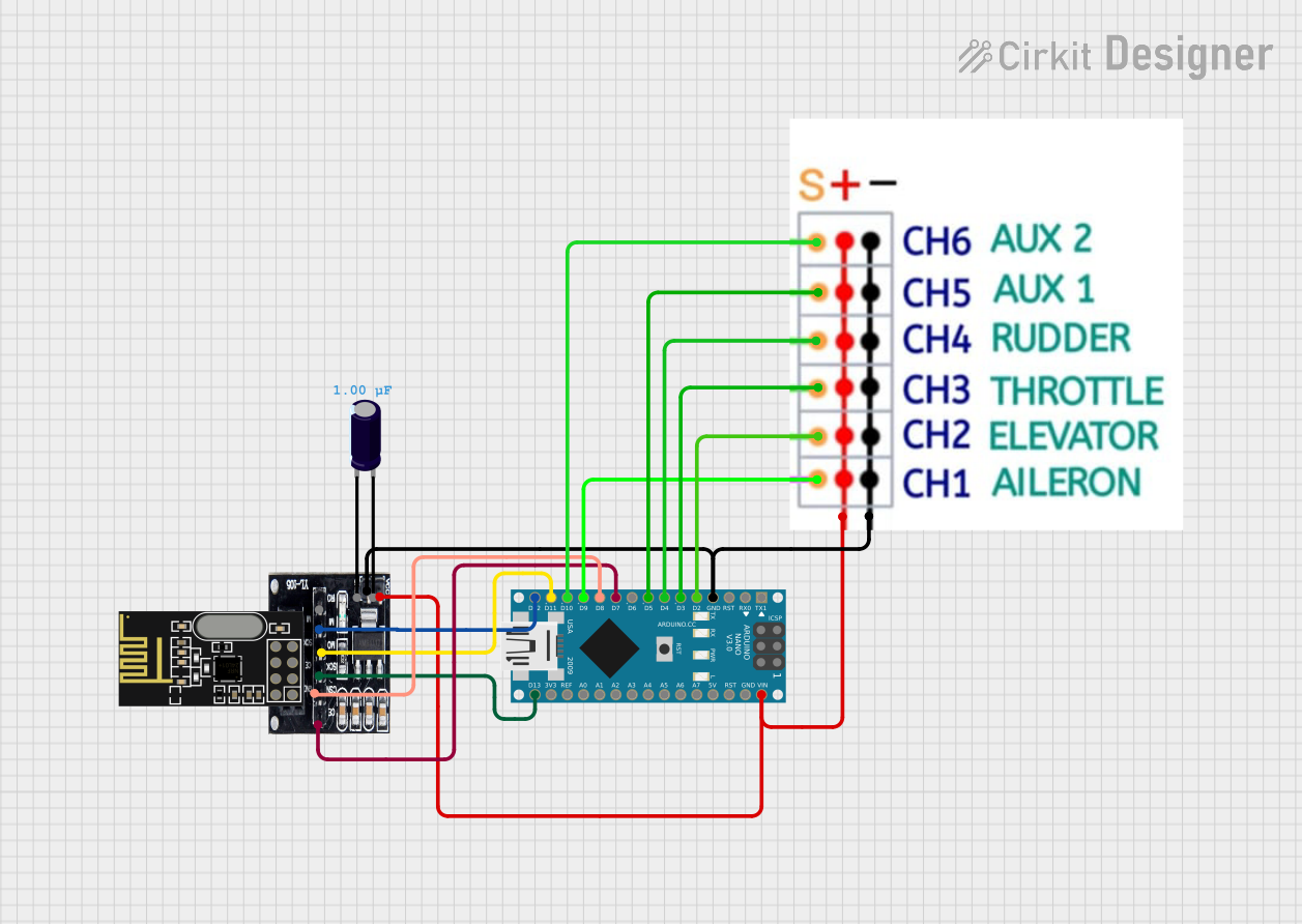
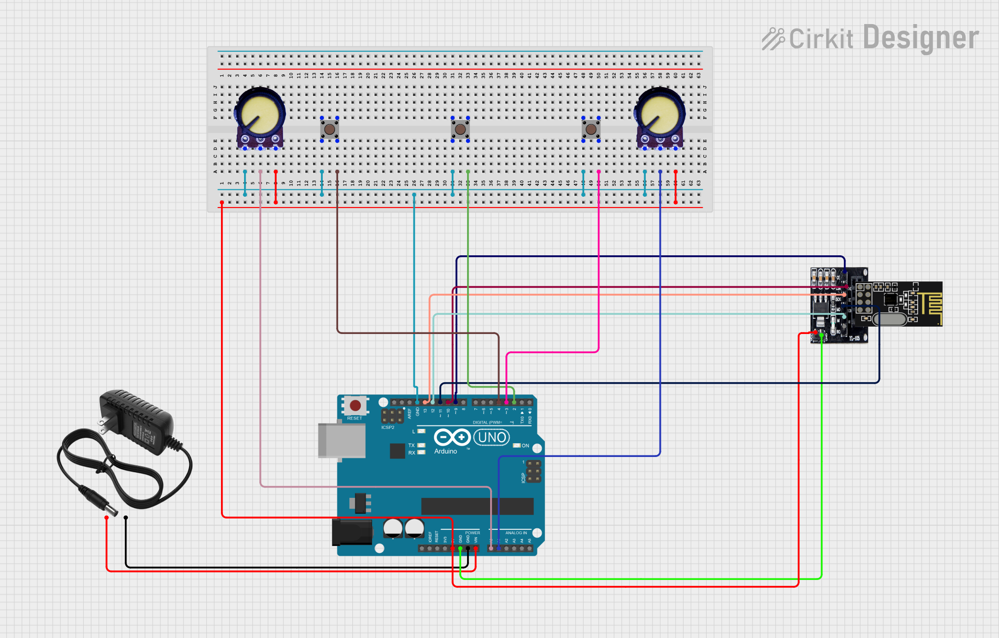
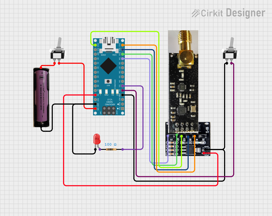
Explore Projects Built with NRF24 Adapter
 Open Project in Cirkit Designer
 Open Project in Cirkit Designer
 Open Project in Cirkit Designer
 Open Project in Cirkit Designer
Explore Projects Built with NRF24 Adapter
Open Project in Cirkit DesignerOpen Project in Cirkit DesignerOpen Project in Cirkit DesignerOpen Project in Cirkit DesignerTechnical Specifications
The NRF24 Adapter is designed to work with the NRF24L01 transceiver module and provides the necessary connections for easy interfacing with microcontrollers. Below are the key technical details:
General Specifications
- Frequency Band: 2.4 GHz ISM
- Operating Voltage: 3.3V (regulated)
- Communication Protocol: SPI (Serial Peripheral Interface)
- Data Rate: Up to 2 Mbps
- Range: Up to 100 meters (line of sight)
- Power Consumption: Low power operation with standby and power-down modes
- Antenna: PCB trace or external antenna (depending on the module)
Pin Configuration and Descriptions
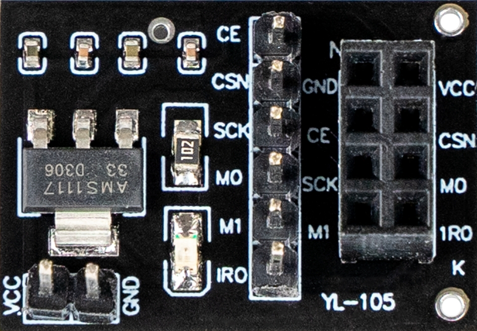
The NRF24 Adapter typically has an 8-pin interface for connecting to a microcontroller. Below is the pinout:
| Pin | Name | Description |
|---|---|---|
| 1 | GND | Ground connection |
| 2 | VCC | Power supply (3.3V regulated) |
| 3 | CE | Chip Enable: Activates the module for transmission or reception |
| 4 | CSN | Chip Select Not: SPI chip select (active low) |
| 5 | SCK | Serial Clock: SPI clock signal |
| 6 | MOSI | Master Out Slave In: SPI data input to the module |
| 7 | MISO | Master In Slave Out: SPI data output from the module |
| 8 | IRQ | Interrupt Request: Indicates events such as data received or transmission done |
Usage Instructions
How to Use the NRF24 Adapter in a Circuit
- Power Supply: Ensure the module is powered with a regulated 3.3V supply. Do not connect it directly to 5V as it may damage the module.
- Connections: Connect the pins of the NRF24 Adapter to the corresponding pins on your microcontroller:
- GND to ground
- VCC to 3.3V
- CE, CSN, SCK, MOSI, and MISO to the respective SPI pins on the microcontroller
- IRQ to an interrupt-capable pin (optional, depending on your application)
- Antenna: If using an external antenna, ensure it is securely connected to the module.
- Software Configuration: Use an appropriate library (e.g., RF24 library for Arduino) to configure and control the module.
Important Considerations and Best Practices
- Voltage Levels: Ensure all logic signals are 3.3V compatible. Use level shifters if interfacing with a 5V microcontroller.
- Decoupling Capacitor: Place a 10 µF capacitor across the VCC and GND pins to stabilize the power supply.
- SPI Speed: Configure the SPI clock speed to a value supported by the NRF24 module (typically up to 10 MHz).
- Distance and Obstacles: The range may vary depending on environmental factors such as walls and interference from other devices.
Example Code for Arduino UNO
Below is an example of how to use the NRF24 Adapter with an Arduino UNO to send and receive data:
#include <SPI.h>
#include <nRF24L01.h>
#include <RF24.h>

// Define the CE and CSN pins for the NRF24 Adapter
#define CE_PIN 9
#define CSN_PIN 10

// Create an RF24 object
RF24 radio(CE_PIN, CSN_PIN);

// Define the address for communication
const byte address[6] = "00001";

void setup() {
  Serial.begin(9600); // Initialize serial communication
  radio.begin();      // Initialize the NRF24 module
  radio.openWritingPipe(address); // Set the address for transmission
  radio.setPALevel(RF24_PA_LOW);  // Set power level to low
  radio.stopListening();          // Set the module to transmit mode
}

void loop() {
  const char text[] = "Hello, World!"; // Data to send
  bool success = radio.write(&text, sizeof(text)); // Send data

  if (success) {
    Serial.println("Data sent successfully!");
  } else {
    Serial.println("Data transmission failed.");
  }

  delay(1000); // Wait for 1 second before sending again
}
Troubleshooting and FAQs
Common Issues and Solutions
Module Not Responding:
- Ensure the power supply is 3.3V and stable.
- Check all connections for proper wiring.
- Verify that the CE and CSN pins are correctly defined in the code.
Short Range or Unstable Communication:
- Use an external antenna if the module supports it.
- Reduce interference by moving the module away from other 2.4 GHz devices.
- Ensure a clear line of sight between the transmitter and receiver.
Data Transmission Fails:
- Verify that the addresses match on both the transmitter and receiver.
- Check the SPI clock speed and ensure it is within the module's specifications.
FAQs
Can I use the NRF24 Adapter with a 5V microcontroller? Yes, but you must use level shifters for the SPI pins to avoid damaging the module.
What is the maximum range of the NRF24 Adapter? The range is up to 100 meters in line-of-sight conditions. Obstacles and interference may reduce this range.
How do I know if the module is working? Use the IRQ pin to monitor events such as successful data transmission or reception. Alternatively, check the return value of the
radio.write()function in your code.
By following this documentation, you can effectively integrate and troubleshoot the NRF24 Adapter in your projects.