Cirkit Designer Logo
Cirkit Designer
Your all-in-one circuit design IDE
Home / 
Component Documentation

How to Use Laser Green Light Module Diode: Examples, Pinouts, and Specs

Image of Laser Green Light Module Diode
Cirkit Designer LogoDesign with Laser Green Light Module Diode in Cirkit Designer

Introduction

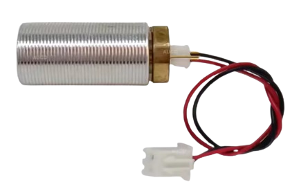
The Laser Green Light Module Diode is a semiconductor device that emits green laser light when an electric current passes through it. This component is widely used in optical applications, laser pointers, and various display technologies due to its high brightness and precision. Its compact size and efficiency make it ideal for integration into a variety of electronic systems.

Common applications include:

  • Laser pointers for presentations and educational purposes
  • Optical communication systems
  • Laser-based measurement and alignment tools
  • Holographic and display technologies
  • DIY electronics and robotics projects

Explore Projects Built with Laser Green Light Module Diode

Use Cirkit Designer to design, explore, and prototype these projects online. Some projects support real-time simulation. Click "Open Project" to start designing instantly!
Battery-Powered Laser Emitter with Solar Charging and LED Indicator
Image of rx: A project utilizing Laser Green Light Module Diode in a practical application
This circuit is a solar-powered laser emitter system with an LED indicator. The solar panel charges a 18650 battery via a TP4056 charging module, and a push button controls the activation of the laser emitter and the LED through a MOSFET switch.
Cirkit Designer LogoOpen Project in Cirkit Designer
Arduino-Controlled Laser Security System with LDR and Buzzer
Image of LASER SECURITY SYSTEM: A project utilizing Laser Green Light Module Diode in a practical application
This circuit features an Arduino UNO interfaced with an LDR module, a laser diode, and a buzzer. The Arduino is programmed to react to light levels detected by the LDR, potentially activating the buzzer or laser diode. The circuit is powered by a 9V battery, with the Arduino regulating power to the laser diode and monitoring the LDR output.
Cirkit Designer LogoOpen Project in Cirkit Designer
Arduino UNO Laser Tripwire Security System with GSM Alert
Image of Laser home security system: A project utilizing Laser Green Light Module Diode in a practical application
This circuit is a laser tripwire security system using an Arduino UNO. When the laser beam is interrupted, the system triggers a buzzer, lights up an LED, and sends an alert via a SIM800L GSM module. The system also includes an LDR module to detect the laser beam and two LEDs to indicate the system status.
Cirkit Designer LogoOpen Project in Cirkit Designer
Arduino-Controlled Laser Security System with LDR and Buzzer
Image of home security system: A project utilizing Laser Green Light Module Diode in a practical application
This circuit features an LDR (Light Dependent Resistor) connected to an Arduino UNO for light sensing, a KY-008 Laser Emitter module controlled by the Arduino via digital pin D2, and a buzzer connected to digital pin D9. The LDR and the laser emitter are powered by the Arduino's 5V output, and all components share a common ground. The provided code skeleton suggests that the Arduino is intended to perform actions based on the LDR readings and control the laser and buzzer, but the specific functionality is not implemented in the given code.
Cirkit Designer LogoOpen Project in Cirkit Designer

Explore Projects Built with Laser Green Light Module Diode

Use Cirkit Designer to design, explore, and prototype these projects online. Some projects support real-time simulation. Click "Open Project" to start designing instantly!
Image of rx: A project utilizing Laser Green Light Module Diode in a practical application
Battery-Powered Laser Emitter with Solar Charging and LED Indicator
This circuit is a solar-powered laser emitter system with an LED indicator. The solar panel charges a 18650 battery via a TP4056 charging module, and a push button controls the activation of the laser emitter and the LED through a MOSFET switch.
Cirkit Designer LogoOpen Project in Cirkit Designer
Image of LASER SECURITY SYSTEM: A project utilizing Laser Green Light Module Diode in a practical application
Arduino-Controlled Laser Security System with LDR and Buzzer
This circuit features an Arduino UNO interfaced with an LDR module, a laser diode, and a buzzer. The Arduino is programmed to react to light levels detected by the LDR, potentially activating the buzzer or laser diode. The circuit is powered by a 9V battery, with the Arduino regulating power to the laser diode and monitoring the LDR output.
Cirkit Designer LogoOpen Project in Cirkit Designer
Image of Laser home security system: A project utilizing Laser Green Light Module Diode in a practical application
Arduino UNO Laser Tripwire Security System with GSM Alert
This circuit is a laser tripwire security system using an Arduino UNO. When the laser beam is interrupted, the system triggers a buzzer, lights up an LED, and sends an alert via a SIM800L GSM module. The system also includes an LDR module to detect the laser beam and two LEDs to indicate the system status.
Cirkit Designer LogoOpen Project in Cirkit Designer
Image of home security system: A project utilizing Laser Green Light Module Diode in a practical application
Arduino-Controlled Laser Security System with LDR and Buzzer
This circuit features an LDR (Light Dependent Resistor) connected to an Arduino UNO for light sensing, a KY-008 Laser Emitter module controlled by the Arduino via digital pin D2, and a buzzer connected to digital pin D9. The LDR and the laser emitter are powered by the Arduino's 5V output, and all components share a common ground. The provided code skeleton suggests that the Arduino is intended to perform actions based on the LDR readings and control the laser and buzzer, but the specific functionality is not implemented in the given code.
Cirkit Designer LogoOpen Project in Cirkit Designer

Technical Specifications

Below are the key technical details of the Laser Green Light Module Diode:

Parameter Value
Wavelength 532 nm (green light)
Operating Voltage 3V to 5V
Operating Current 200 mA (typical)
Output Power <5 mW (Class IIIa laser)
Beam Divergence <1.5 mrad
Operating Temperature -10°C to 40°C
Dimensions 12 mm (diameter) x 45 mm (length)

Pin Configuration and Descriptions

The Laser Green Light Module Diode typically has three pins or wires for connection:

Pin/Wire Description
VCC Positive power supply (3V to 5V)
GND Ground connection
TTL/Control Optional input for modulation or on/off control

Note: Some modules may only have two wires (VCC and GND) if they lack TTL modulation functionality.

Usage Instructions

How to Use the Component in a Circuit

  1. Power Supply: Connect the VCC pin to a stable DC power source (3V to 5V). Ensure the power supply can provide sufficient current (at least 200 mA).
  2. Ground Connection: Connect the GND pin to the ground of your circuit.
  3. TTL/Control Pin (if available): Use this pin to modulate the laser output. A HIGH signal (e.g., 5V) turns the laser ON, while a LOW signal (e.g., 0V) turns it OFF.

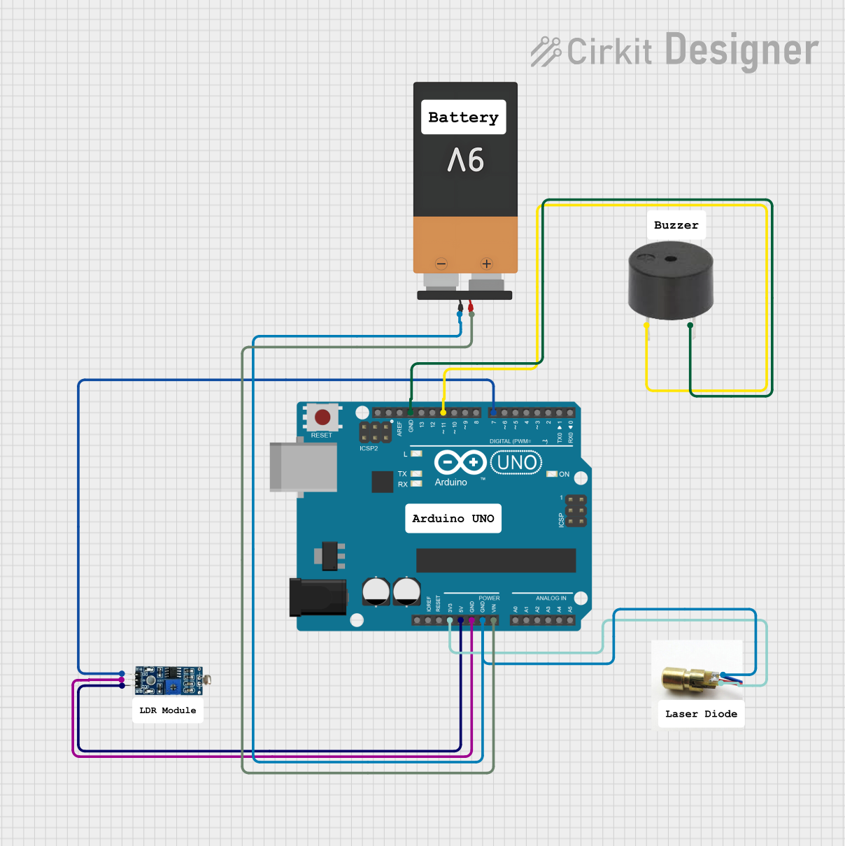
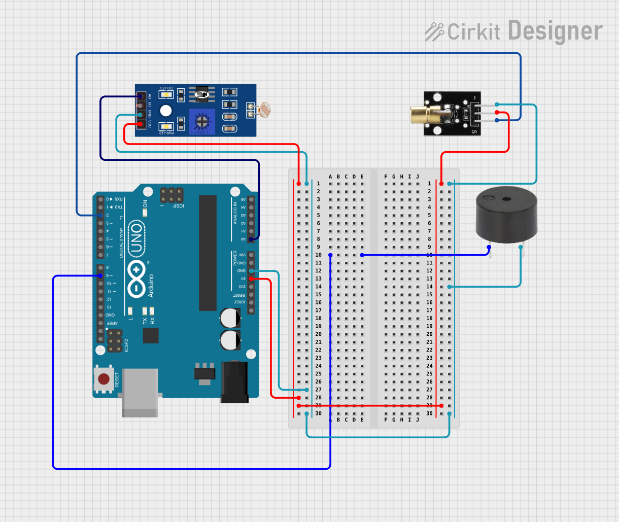
Example Circuit with Arduino UNO

Below is an example of how to connect and control the Laser Green Light Module Diode using an Arduino UNO:

Circuit Connections:

  • Connect the VCC pin of the laser module to the 5V pin on the Arduino.
  • Connect the GND pin of the laser module to the GND pin on the Arduino.
  • If the module has a TTL/Control pin, connect it to a digital pin on the Arduino (e.g., pin 9).

Arduino Code:

// Laser Green Light Module Control with Arduino UNO
// This code turns the laser ON for 1 second and OFF for 1 second in a loop.

const int laserPin = 9; // TTL/Control pin connected to Arduino digital pin 9

void setup() {
  pinMode(laserPin, OUTPUT); // Set the laser pin as an output
}

void loop() {
  digitalWrite(laserPin, HIGH); // Turn the laser ON
  delay(1000); // Wait for 1 second
  digitalWrite(laserPin, LOW); // Turn the laser OFF
  delay(1000); // Wait for 1 second
}

Important Considerations and Best Practices

  • Eye Safety: Always avoid direct eye exposure to the laser beam. Use appropriate laser safety goggles if necessary.
  • Heat Management: Prolonged use may cause the module to heat up. Ensure proper ventilation or use a heat sink if required.
  • Power Supply: Use a regulated power supply to prevent voltage spikes that could damage the diode.
  • Modulation: If using the TTL/Control pin, ensure the input signal does not exceed the module's voltage rating.

Troubleshooting and FAQs

Common Issues and Solutions

  1. Laser Does Not Turn On:

    • Check the power supply voltage and current. Ensure it meets the module's requirements.
    • Verify all connections, especially VCC and GND.
    • If using the TTL/Control pin, ensure it is receiving the correct signal.
  2. Laser Output is Dim:

    • Ensure the power supply is stable and not underpowered.
    • Check for any obstructions in the laser's optical path.
    • Verify that the operating temperature is within the specified range.
  3. Module Overheats:

    • Reduce the operating time or add a heat sink to dissipate heat.
    • Ensure proper ventilation around the module.
  4. Beam is Misaligned or Unstable:

    • Check the mounting of the module to ensure it is secure.
    • Avoid vibrations or shocks that could affect the alignment.

FAQs

Q: Can I power the laser module directly from a 9V battery?
A: No, the module is designed for a voltage range of 3V to 5V. Using a 9V battery without a voltage regulator may damage the diode.

Q: Is the laser safe for use in DIY projects?
A: Yes, but always follow laser safety guidelines. Avoid direct eye exposure and use the module responsibly.

Q: Can I use PWM to control the laser brightness?
A: Yes, if the module has a TTL/Control pin, you can use PWM signals to modulate the laser's intensity.

Q: What is the maximum distance the laser can project?
A: The effective range depends on environmental conditions and the module's output power. For a typical <5 mW module, the beam can be visible up to several hundred meters in low-light conditions.

By following this documentation, you can safely and effectively integrate the Laser Green Light Module Diode into your projects.