
How to Use TPS61200: Examples, Pinouts, and Specs
 Design with TPS61200 in Cirkit Designer
Introduction
The TPS61200 is a high-efficiency boost converter designed to step up low input voltages to higher output voltages. This makes it ideal for battery-powered applications where efficient power management is critical. With its wide input voltage range, adjustable output voltage, and low quiescent current, the TPS61200 is a versatile solution for portable devices, wearable electronics, and other low-power systems.
Explore Projects Built with TPS61200
 Open Project in Cirkit Designer
 Open Project in Cirkit Designer
 Open Project in Cirkit Designer
 Open Project in Cirkit Designer
Explore Projects Built with TPS61200
Open Project in Cirkit DesignerOpen Project in Cirkit DesignerOpen Project in Cirkit DesignerOpen Project in Cirkit DesignerCommon Applications and Use Cases
- Portable devices powered by single-cell batteries (e.g., Li-ion, NiMH, or alkaline)
- Wearable electronics
- Low-power microcontroller systems
- Energy harvesting applications
- LED drivers and backlighting
Technical Specifications
Key Technical Details
- Input Voltage Range: 0.3 V to 5.5 V
- Output Voltage Range: Adjustable from 1.8 V to 5.5 V
- Maximum Output Current: Up to 600 mA (depending on input/output voltage conditions)
- Efficiency: Up to 96%
- Quiescent Current: 55 µA (typical)
- Switching Frequency: 1 MHz
- Package: 10-pin VSON (3 mm × 3 mm)
Pin Configuration and Descriptions
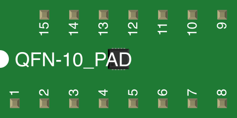
The TPS61200 is available in a 10-pin VSON package. Below is the pin configuration:
| Pin Number | Pin Name | Description |
|---|---|---|
| 1 | SW | Switch pin. Connect to the inductor. |
| 2 | GND | Ground pin. Connect to system ground. |
| 3 | FB | Feedback pin. Used to set the output voltage via an external resistor divider. |
| 4 | EN | Enable pin. Logic high enables the device; logic low disables it. |
| 5 | PGND | Power ground. Connect to the ground plane. |
| 6 | VIN | Input voltage pin. Connect to the power source. |
| 7 | VOUT | Output voltage pin. Connect to the load and output capacitor. |
| 8 | PS | Power save mode pin. Logic high enables power save mode. |
| 9 | L | Inductor connection pin. |
| 10 | NC | No connection. Leave this pin floating. |
Usage Instructions
How to Use the TPS61200 in a Circuit
- Input and Output Capacitors:
- Place a low-ESR ceramic capacitor (e.g., 10 µF) at the input (VIN) and output (VOUT) pins to ensure stable operation.
- Inductor Selection:
- Use an inductor with a value between 1 µH and 4.7 µH. Ensure the inductor's current rating exceeds the peak current of the TPS61200.
- Feedback Resistor Divider:
- Use two resistors to set the output voltage. The formula is: [ V_{OUT} = V_{REF} \times \left(1 + \frac{R1}{R2}\right) ] where ( V_{REF} = 0.5 , \text{V} ).
- Enable Pin:
- Connect the EN pin to VIN or a GPIO pin of a microcontroller to enable or disable the device.
- Power Save Mode:
- Connect the PS pin to logic high to enable power save mode for light load conditions.
Example Circuit
Below is a basic circuit diagram for the TPS61200:
VIN ----[10 µF]----+----[Inductor]----+---- VOUT
                   |                  |
                  GND                GND
Arduino UNO Example Code
The TPS61200 can be controlled using an Arduino UNO to enable or disable the boost converter. Below is an example code snippet:
// Define the pin connected to the EN (Enable) pin of TPS61200
const int enablePin = 7;

void setup() {
  // Set the enable pin as an output
  pinMode(enablePin, OUTPUT);

  // Enable the TPS61200 by setting the pin HIGH
  digitalWrite(enablePin, HIGH);
}

void loop() {
  // Example: Toggle the TPS61200 every 5 seconds
  digitalWrite(enablePin, HIGH); // Enable the boost converter
  delay(5000);                   // Wait for 5 seconds
  digitalWrite(enablePin, LOW);  // Disable the boost converter
  delay(5000);                   // Wait for 5 seconds
}
Important Considerations and Best Practices
- Ensure proper PCB layout with short and wide traces for the power path (VIN, VOUT, SW, and GND).
- Place the input and output capacitors as close as possible to the VIN and VOUT pins.
- Avoid exceeding the maximum input voltage (5.5 V) or output current (600 mA).
- Use a shielded inductor to minimize electromagnetic interference (EMI).
Troubleshooting and FAQs
Common Issues and Solutions
Output Voltage is Unstable or Incorrect:
- Check the feedback resistor values and ensure they are calculated correctly.
- Verify that the input and output capacitors have the correct values and are low-ESR types.
- Ensure the inductor value and current rating meet the design requirements.
Device Overheats:
- Verify that the load current does not exceed the maximum output current.
- Check for proper PCB layout and adequate thermal dissipation.
No Output Voltage:
- Ensure the EN pin is pulled high to enable the device.
- Verify that the input voltage is within the specified range (0.3 V to 5.5 V).
- Check for proper soldering and connections on the PCB.
High Ripple on Output Voltage:
- Use a higher-value output capacitor or a capacitor with lower ESR.
- Ensure the inductor is not saturating under load conditions.
FAQs
Q1: Can the TPS61200 operate with a single alkaline battery?
A1: Yes, the TPS61200 can operate with a single alkaline battery, as its input voltage range starts from 0.3 V.
Q2: How do I calculate the feedback resistor values for a specific output voltage?
A2: Use the formula ( V_{OUT} = V_{REF} \times (1 + R1 / R2) ), where ( V_{REF} = 0.5 , \text{V} ). Choose R2 (e.g., 100 kΩ) and calculate R1 accordingly.
Q3: What happens if the PS pin is left floating?
A3: If the PS pin is left floating, the device may not operate correctly. It is recommended to connect it to either logic high or low.
Q4: Can the TPS61200 be used to power an Arduino UNO?
A4: Yes, the TPS61200 can step up a low input voltage (e.g., from a battery) to 5 V to power an Arduino UNO. Ensure the output current meets the Arduino's power requirements.