How to Use Tristate PCB: Examples, Pinouts, and Specs
Introduction
The Tristate PCB is a specialized printed circuit board designed to support tristate logic. Tristate logic allows a single output to exist in one of three states: high, low, or high-impedance (disconnected). This high-impedance state enables multiple devices to share the same output line without interference, making the Tristate PCB ideal for applications requiring bus systems, multiplexing, or shared communication lines.
Explore Projects Built with Tristate PCB


Explore Projects Built with Tristate PCB
Common Applications and Use Cases
- Digital communication buses (e.g., I2C, SPI, or parallel buses)
- Multiplexing signals in microcontroller or FPGA designs
- Shared data lines in memory systems
- Enabling multiple devices to communicate over a single line without conflict
Technical Specifications
Key Technical Details
- Voltage Range: 3.3V to 5V (compatible with most logic families)
- Current Handling: Up to 20mA per output pin
- High-Impedance State Leakage Current: ≤ 1µA
- Operating Temperature: -40°C to 85°C
- PCB Dimensions: 50mm x 50mm
- Supported Logic Families: TTL, CMOS
- Connector Type: Standard 2.54mm pitch headers
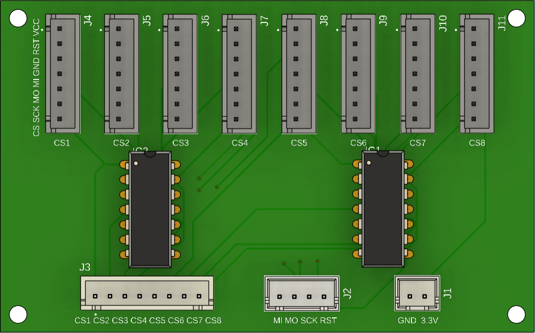
Pin Configuration and Descriptions
The Tristate PCB typically includes a set of input, output, and control pins. Below is the pin configuration:
| Pin Name | Type | Description |
|---|---|---|
VCC |
Power | Power supply input (3.3V or 5V). |
GND |
Ground | Ground connection. |
INx |
Input | Input signal pins (x = 1, 2, 3, etc.). |
OUTx |
Output | Output signal pins corresponding to each input. |
ENx |
Control Signal | Enable pins for tristate control. High = Active, Low = High-Impedance State. |
Usage Instructions
How to Use the Tristate PCB in a Circuit
- Power the PCB: Connect the
VCCpin to a 3.3V or 5V power source and theGNDpin to ground. - Connect Input Signals: Attach your input signals to the
INxpins. - Connect Output Signals: Connect the
OUTxpins to the desired output devices or bus lines. - Control the Tristate Logic: Use the
ENxpins to control the state of each output:- Set
ENxhigh to enable the corresponding output (OUTx) to follow the input (INx). - Set
ENxlow to place the output in a high-impedance state, effectively disconnecting it.
- Set
Important Considerations and Best Practices
- Avoid Bus Contention: Ensure that only one device drives the shared bus at any given time. Use the
ENxpins to manage this. - Pull-Up or Pull-Down Resistors: For unused inputs or control pins, use pull-up or pull-down resistors to prevent floating states.
- Voltage Compatibility: Verify that the input and output voltage levels are compatible with the devices connected to the PCB.
- Decoupling Capacitors: Place decoupling capacitors (e.g., 0.1µF) near the
VCCpin to stabilize the power supply.
Example: Using the Tristate PCB with an Arduino UNO
Below is an example of how to use the Tristate PCB with an Arduino UNO to control a shared data line:
// Define pin connections for the Tristate PCB
const int enablePin = 7;  // ENx pin connected to Arduino digital pin 7
const int inputPin = 8;   // INx pin connected to Arduino digital pin 8
const int outputPin = 9;  // OUTx pin connected to the shared data line

void setup() {
  pinMode(enablePin, OUTPUT); // Set enable pin as output
  pinMode(inputPin, OUTPUT);  // Set input pin as output
  pinMode(outputPin, INPUT);  // Set output pin as input (shared line)
}

void loop() {
  // Enable the tristate output
  digitalWrite(enablePin, HIGH); // Enable output (active state)
  digitalWrite(inputPin, HIGH); // Set input to HIGH
  delay(1000);                  // Wait for 1 second

  // Disable the tristate output (high-impedance state)
  digitalWrite(enablePin, LOW); // Disable output (high-impedance)
  delay(1000);                  // Wait for 1 second
}
Troubleshooting and FAQs
Common Issues and Solutions
Output Not Responding to Input
- Cause: The
ENxpin is not set to the correct state. - Solution: Ensure the
ENxpin is set high to enable the output.
- Cause: The
Bus Contention or Signal Interference
- Cause: Multiple devices are driving the shared bus simultaneously.
- Solution: Use the
ENxpins to ensure only one device drives the bus at a time.
Floating or Unstable Signals
- Cause: Unused inputs or control pins are left floating.
- Solution: Use pull-up or pull-down resistors to stabilize unused pins.
High-Impedance State Not Working
- Cause: Incorrect wiring or faulty control signal.
- Solution: Verify the wiring and ensure the
ENxpin is set low to activate the high-impedance state.
FAQs
Q: Can the Tristate PCB handle bidirectional communication?
A: Yes, as long as the control logic ensures only one device drives the bus at a time.Q: What happens if I leave the
ENxpin floating?
A: The output state may become unpredictable. Always tie theENxpin to a defined logic level.Q: Can I use the Tristate PCB with 12V logic?
A: No, the Tristate PCB is designed for 3.3V or 5V logic levels only.Q: How many tristate channels does the PCB support?
A: The number of channels depends on the specific model. Refer to the product datasheet for details.