Cirkit Designer
Your all-in-one circuit design IDE
Home /
Component Documentation
How to Use 48v to 5v: Examples, Pinouts, and Specs
Introduction
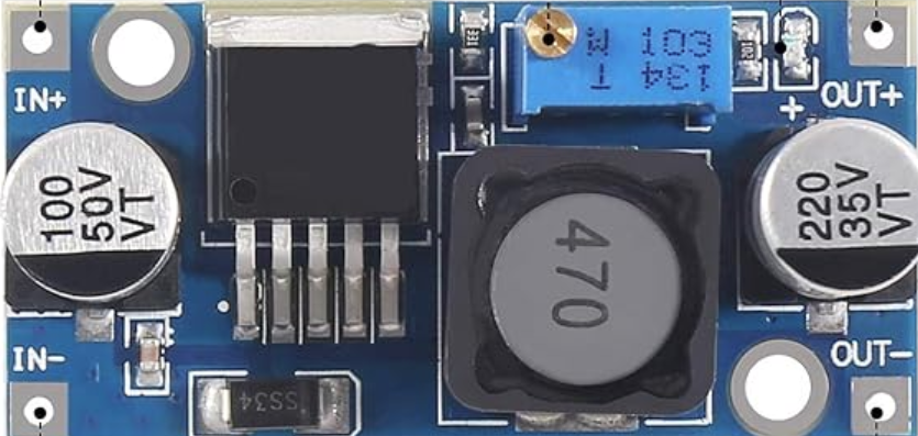
The 48V to 5V Step-Down Voltage Regulator is an electronic component designed to convert a high input voltage of 48V DC to a lower output voltage of 5V DC. This type of regulator is commonly used in industrial systems, automotive applications, and any electronic project where a 5V power supply is needed from a 48V source.
Explore Projects Built with 48v to 5v
Battery-Powered DC-DC Converter System for Multi-Voltage Power Distribution

This circuit converts a 38.5V battery output to multiple lower voltage levels using a series of DC-DC converters and a power module. It includes an emergency stop switch for safety and distributes power to various components such as a relay module, USB ports, and a bus servo adaptor.
12V to 5V Power Supply with LED Indicator and Push Switch

This circuit is a 12V to 5V regulated power supply with an LED indicator. It uses a 5408 diode for reverse polarity protection, an LM340T5 7805 voltage regulator to step down the voltage to 5V, and a push switch to control the LED indicator. The circuit also includes capacitors for filtering and a resistor to limit the current through the LED.
24V to 5V Power Supply with 7805 Voltage Regulator and Bridge Rectifier

This circuit converts 220V AC to 5V DC using a power transformer, a bridge rectifier, and a 7805 voltage regulator. The transformer steps down the voltage to 24V AC, which is then rectified to DC by the bridge rectifier. The 7805 regulator further stabilizes the output to 5V DC, with additional filtering provided by capacitors and a resistor.
Battery-Powered USB Charger with LED Indicator and DC Motor

This circuit converts AC power to DC using a bridge rectifier and regulates the voltage to 5V with a 7805 voltage regulator. It powers a USB port and indicates power status with an LED, while also providing a charging interface through a multi-charging cable.
Explore Projects Built with 48v to 5v
Battery-Powered DC-DC Converter System for Multi-Voltage Power Distribution
This circuit converts a 38.5V battery output to multiple lower voltage levels using a series of DC-DC converters and a power module. It includes an emergency stop switch for safety and distributes power to various components such as a relay module, USB ports, and a bus servo adaptor.
12V to 5V Power Supply with LED Indicator and Push Switch
This circuit is a 12V to 5V regulated power supply with an LED indicator. It uses a 5408 diode for reverse polarity protection, an LM340T5 7805 voltage regulator to step down the voltage to 5V, and a push switch to control the LED indicator. The circuit also includes capacitors for filtering and a resistor to limit the current through the LED.
24V to 5V Power Supply with 7805 Voltage Regulator and Bridge Rectifier
This circuit converts 220V AC to 5V DC using a power transformer, a bridge rectifier, and a 7805 voltage regulator. The transformer steps down the voltage to 24V AC, which is then rectified to DC by the bridge rectifier. The 7805 regulator further stabilizes the output to 5V DC, with additional filtering provided by capacitors and a resistor.
Battery-Powered USB Charger with LED Indicator and DC Motor
This circuit converts AC power to DC using a bridge rectifier and regulates the voltage to 5V with a 7805 voltage regulator. It powers a USB port and indicates power status with an LED, while also providing a charging interface through a multi-charging cable.
Common Applications and Use Cases
- Powering 5V microcontrollers or logic circuits from a 48V bus
- Providing a 5V supply for sensors and actuators in industrial automation
- Converting 48V battery power to 5V for USB devices or LED lighting
- Use in electric vehicles or solar power systems where 48V is standard
Technical Specifications
Key Technical Details
- Input Voltage (Vin): 48V DC
- Output Voltage (Vout): 5V DC
- Maximum Output Current: X Amps
- Efficiency: Up to XX%
- Operating Temperature Range: -XX to XX°C
- Protection Features: Overcurrent, Overvoltage, Thermal Shutdown
Pin Configuration and Descriptions
| Pin Number | Name | Description |
|---|---|---|
| 1 | VIN | Input voltage (48V) |
| 2 | GND | Ground connection |
| 3 | VOUT | Regulated output voltage (5V) |
| 4 | EN | Enable pin (active high) |
| 5 | FB | Feedback pin (if applicable) |
Usage Instructions
How to Use the Component in a Circuit
- Connecting Input Voltage: Connect the 48V source to the VIN and GND pins, ensuring correct polarity.
- Drawing Output Voltage: Connect your 5V-required device or circuit to the VOUT and GND pins.
- Enabling the Regulator: If the regulator has an enable pin (EN), connect it to a high logic level to turn on the regulator. If not required, it can be tied to VIN through a pull-up resistor.
- Heat Management: Depending on the current draw, a heatsink may be necessary to dissipate heat and maintain efficiency.
Important Considerations and Best Practices
- Ensure the input voltage does not exceed the maximum rating of the regulator.
- Avoid drawing more current than the maximum output rating to prevent overheating and potential damage.
- Use capacitors at the input and output for filtering if the application is sensitive to voltage spikes or noise.
- Always follow the manufacturer's recommendations for layout, grounding, and heat dissipation.
Troubleshooting and FAQs
Common Issues Users Might Face
- Output Voltage is Too Low or Unstable: Check for overloading or insufficient input voltage.
- Regulator Overheating: Ensure the current draw is within limits and improve heat dissipation.
- No Output Voltage: Verify connections, input voltage, and that the EN pin is correctly configured.
Solutions and Tips for Troubleshooting
- If the output voltage is incorrect, verify the input voltage and load conditions.
- For overheating issues, reduce the load or improve cooling with a heatsink or airflow.
- In case of no output, check for short circuits, proper enable pin voltage, and that the regulator is not in a protection mode.
Example Connection with Arduino UNO
// Example code to monitor the 5V output from the step-down regulator
// using an Arduino UNO. The regulator's VOUT is connected to an analog pin.

const int analogPin = A0; // Connect the 5V output to A0

void setup() {
  Serial.begin(9600);
}

void loop() {
  int sensorValue = analogRead(analogPin); // Read the voltage
  float voltage = sensorValue * (5.0 / 1023.0); // Convert to voltage
  Serial.print("Voltage: ");
  Serial.println(voltage); // Print the voltage
  delay(1000); // Wait for a second
}
Note: This code assumes that the 5V output from the regulator is within the range that the Arduino analog pin can measure. If the regulator's output is higher than 5V, a voltage divider or level shifter is required to bring the voltage within a safe range for the Arduino.
Remember to wrap the code comments as needed to limit line length to 80 characters.