How to Use Arduino Fio (Funnel I/O): Examples, Pinouts, and Specs
Introduction
The Arduino Fio (Funnel I/O) is a compact microcontroller board designed for wireless applications. It is based on the ATmega328P microcontroller and is compatible with the Arduino Integrated Development Environment (IDE). The board is particularly suitable for projects that require remote sensing, telemetry, and other applications where wireless communication is essential.
Explore Projects Built with Arduino Fio (Funnel I/O)
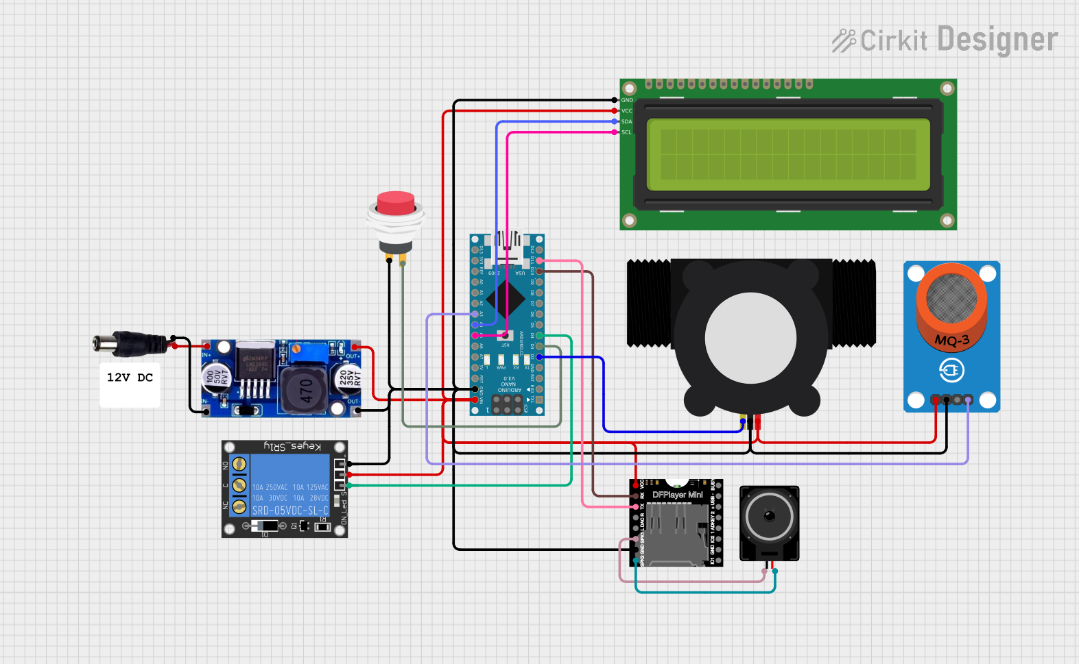
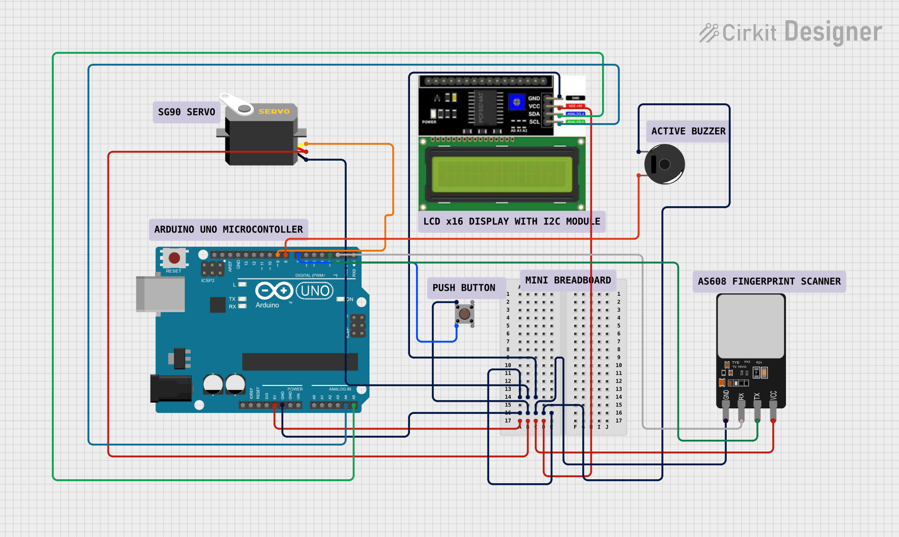
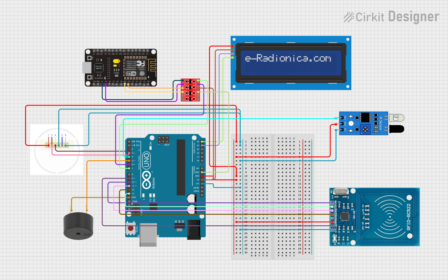

Explore Projects Built with Arduino Fio (Funnel I/O)
Common Applications and Use Cases
- Remote data logging
- Telemetry systems for drones or RC vehicles
- Wireless sensor networks
- Prototyping Internet of Things (IoT) devices
- Educational projects to learn about wireless communication
Technical Specifications
Key Technical Details
- Microcontroller: ATmega328P
- Operating Voltage: 3.3V
- Input Voltage: 3.35-12V (battery), 5V (USB)
- Digital I/O Pins: 14 (of which 6 provide PWM output)
- Analog Input Pins: 8
- DC Current per I/O Pin: 40 mA
- Flash Memory: 32 KB (ATmega328P) of which 2 KB used by bootloader
- SRAM: 2 KB (ATmega328P)
- EEPROM: 1 KB (ATmega328P)
- Clock Speed: 8 MHz
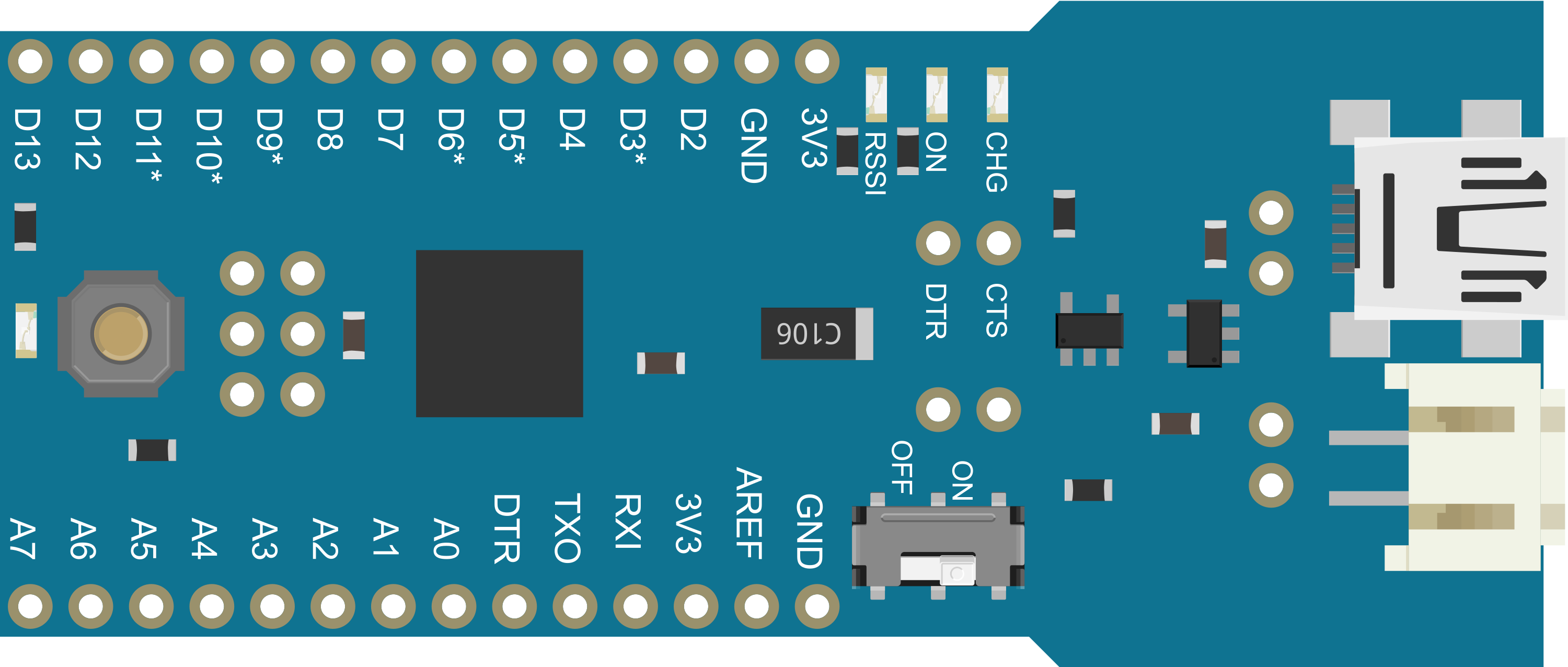
Pin Configuration and Descriptions
| Pin Number | Function | Description |
|---|---|---|
| 1-14 | Digital I/O | Digital input/output pins, PWM on 3, 5, 6, 9, 10, and 11 |
| A0-A7 | Analog Input | Analog input pins |
| AREF | Analog Reference | Reference voltage for the analog inputs |
| GND | Ground | Ground pin |
| RST | Reset | Used to reset the microcontroller |
| 3V3 | 3.3V Supply | 3.3V output from the onboard regulator |
| VBAT | Battery Input | Battery input for an external battery |
| RX0, TX0 | Serial Communication | Receive and transmit serial data |
Usage Instructions
How to Use the Component in a Circuit
Powering the Arduino Fio: You can power the Arduino Fio through a battery connected to the
VBATpin or via the USB connection. Ensure that the battery voltage is within the specified range.Programming the Arduino Fio: Connect the board to your computer using a USB cable. Select 'Arduino Fio' from the Tools > Board menu in the Arduino IDE. Use the correct serial port from Tools > Port.
Connecting I/O Pins: Connect sensors, actuators, or other components to the digital and analog pins as required for your project. Remember to configure the pins appropriately in your sketch (code).
Wireless Communication: To use the wireless capabilities, attach a compatible wireless module, such as the XBee, to the socket provided on the board.
Important Considerations and Best Practices
- Always ensure that the power supply is within the recommended voltage range to prevent damage to the board.
- When using wireless modules, be aware of the power requirements and ensure that the Arduino Fio can provide sufficient current.
- Use proper decoupling capacitors close to the power pins of the board to reduce noise and power fluctuations.
- Avoid placing the board in environments with extreme temperatures or humidity.
Troubleshooting and FAQs
Common Issues
- Board not recognized by the computer: Ensure that the drivers are installed correctly and that the USB cable is functioning.
- Wireless module not communicating: Verify that the module is seated correctly and configured to communicate with the corresponding wireless receiver.
Solutions and Tips for Troubleshooting
- If the board is not recognized, try using a different USB cable or port.
- For wireless communication issues, ensure that the baud rate and configuration settings match between the modules.
- Check the battery voltage if the board behaves erratically or resets unexpectedly.
FAQs
Q: Can I power the Arduino Fio with a 9V battery? A: Yes, you can power it with a battery within the 3.35-12V range.
Q: How do I upload sketches to the Arduino Fio? A: Use a USB cable to connect the board to your computer and upload sketches through the Arduino IDE.
Q: Does the Arduino Fio have onboard wireless? A: The Fio has a socket for XBee modules but does not have built-in wireless capabilities.
Q: What should I do if I'm getting noisy readings from my sensors? A: Ensure that your power supply is stable and use decoupling capacitors. Also, keep the sensor wiring away from high-current traces.
Example Code for Arduino UNO
// Blink an LED connected to pin 13 of the Arduino Fio

void setup() {
  pinMode(13, OUTPUT); // Initialize digital pin 13 as an output.
}

void loop() {
  digitalWrite(13, HIGH); // Turn the LED on
  delay(1000);           // Wait for a second
  digitalWrite(13, LOW);  // Turn the LED off
  delay(1000);           // Wait for a second
}
Note: The example code provided is for the Arduino UNO, which is compatible with the Arduino Fio. Make sure to select the correct board from the Arduino IDE when uploading the code.