
How to Use Relay Omron MY2N: Examples, Pinouts, and Specs
 Design with Relay Omron MY2N in Cirkit Designer
Introduction
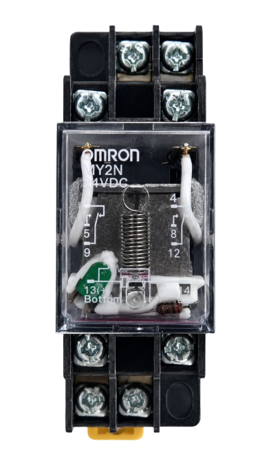
The Omron MY2N is a general-purpose relay designed for reliable switching of high currents and voltages. It features a compact design and a double-pole double-throw (DPDT) configuration, making it versatile for a wide range of applications. This relay is commonly used in automation, industrial control systems, home appliances, and signal switching circuits. Its transparent housing allows for easy visual inspection of the relay's operation, ensuring reliability and ease of maintenance.
Explore Projects Built with Relay Omron MY2N
 Open Project in Cirkit Designer
 Open Project in Cirkit Designer
 Open Project in Cirkit Designer
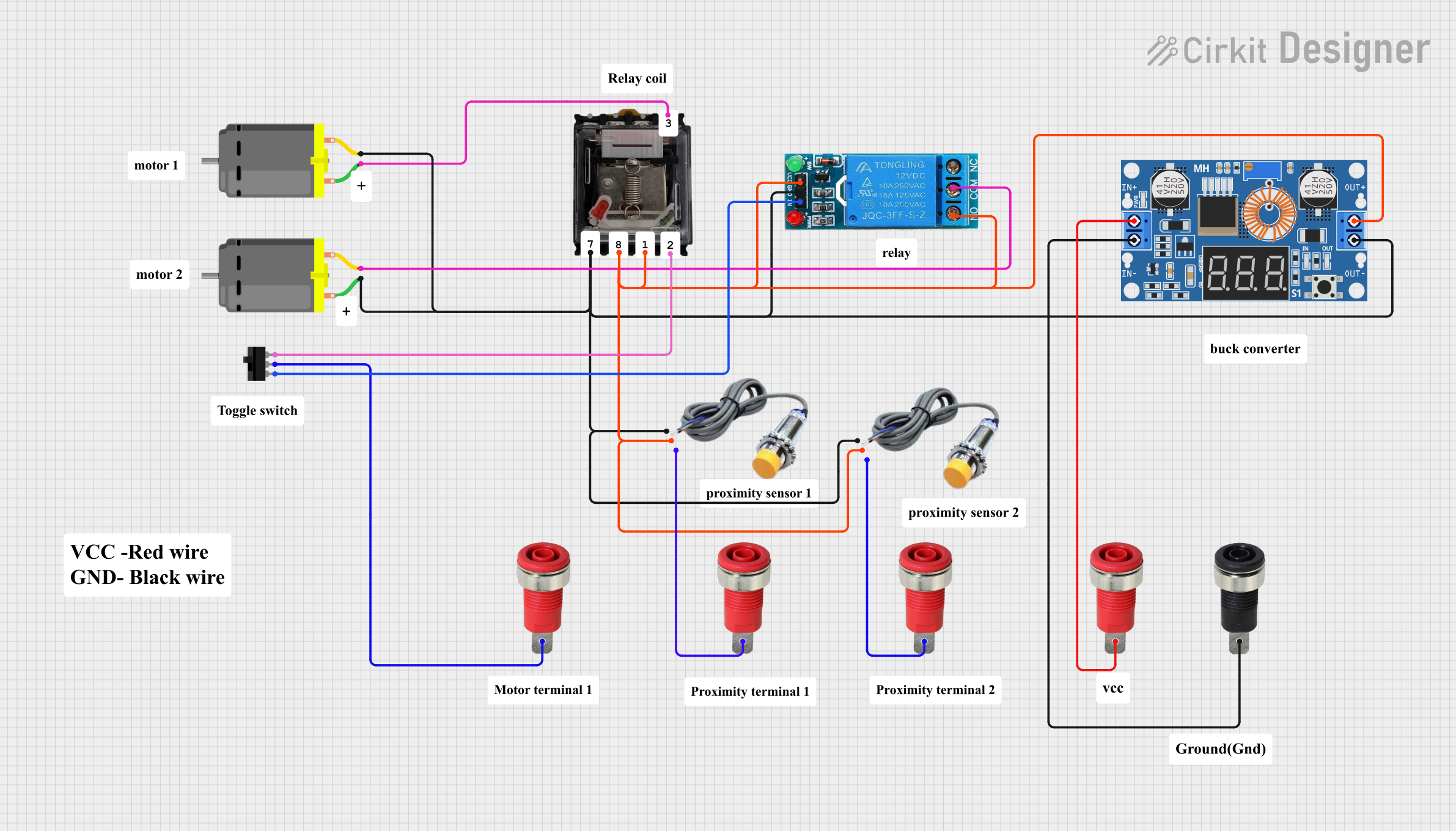 Open Project in Cirkit Designer
Explore Projects Built with Relay Omron MY2N
Open Project in Cirkit DesignerOpen Project in Cirkit DesignerOpen Project in Cirkit DesignerOpen Project in Cirkit DesignerCommon Applications
- Industrial automation and control systems
- Signal switching in electronic circuits
- Home appliances and HVAC systems
- Motor control and protection circuits
- Power distribution and load management
Technical Specifications
Key Technical Details
| Parameter | Value |
|---|---|
| Manufacturer | Omron |
| Model | MY2N |
| Contact Configuration | DPDT (Double-Pole Double-Throw) |
| Coil Voltage Range | 6V DC, 12V DC, 24V DC, 48V DC, 110V AC, 220V AC |
| Contact Rating | 5A at 250V AC / 30V DC |
| Coil Power Consumption | Approximately 0.9W (DC) / 1.2VA (AC) |
| Insulation Resistance | 100 MΩ minimum (at 500V DC) |
| Dielectric Strength | 2000V AC for 1 minute |
| Operating Temperature | -40°C to 70°C |
| Mechanical Durability | 50 million operations (minimum) |
| Electrical Durability | 500,000 operations (minimum) |
Pin Configuration and Descriptions
The Omron MY2N relay has 8 pins arranged in a standard configuration. Below is the pinout description:
| Pin Number | Description |
|---|---|
| 1 | Coil Terminal A |
| 2 | Coil Terminal B |
| 3 | Common Terminal for Pole 1 (COM1) |
| 4 | Normally Closed Contact for Pole 1 (NC1) |
| 5 | Normally Open Contact for Pole 1 (NO1) |
| 6 | Common Terminal for Pole 2 (COM2) |
| 7 | Normally Closed Contact for Pole 2 (NC2) |
| 8 | Normally Open Contact for Pole 2 (NO2) |
Usage Instructions
How to Use the Omron MY2N in a Circuit
- Power the Coil: Connect the coil terminals (pins 1 and 2) to the appropriate voltage source. Ensure the voltage matches the relay's rated coil voltage (e.g., 12V DC or 24V DC).
- Connect the Load:
- For Pole 1: Connect the load to the common terminal (pin 3) and either the normally closed (pin 4) or normally open (pin 5) contact, depending on the desired operation.
- For Pole 2: Similarly, connect the load to the common terminal (pin 6) and either the normally closed (pin 7) or normally open (pin 8) contact.
- Switching Operation: When the coil is energized, the relay switches from the normally closed (NC) contact to the normally open (NO) contact. When the coil is de-energized, it returns to its default state.
Important Considerations and Best Practices
- Diode Protection: When using a DC coil, connect a flyback diode across the coil terminals to protect the circuit from voltage spikes caused by the collapsing magnetic field when the relay is de-energized.
- Contact Ratings: Ensure the load current and voltage do not exceed the relay's contact ratings to avoid damage or failure.
- Mounting: Use a compatible socket or PCB mount for secure installation. Ensure proper insulation and spacing between pins to prevent short circuits.
- Testing: Before integrating the relay into a circuit, test its operation using a multimeter to verify continuity between the contacts.
Example: Using the MY2N with an Arduino UNO
Below is an example of how to control the Omron MY2N relay using an Arduino UNO:
// Example: Controlling Omron MY2N Relay with Arduino UNO
// Pin 7 of Arduino is used to control the relay

const int relayPin = 7; // Define the pin connected to the relay module

void setup() {
  pinMode(relayPin, OUTPUT); // Set relay pin as output
  digitalWrite(relayPin, LOW); // Ensure relay is off at startup
}

void loop() {
  digitalWrite(relayPin, HIGH); // Turn relay on
  delay(1000); // Keep relay on for 1 second
  digitalWrite(relayPin, LOW); // Turn relay off
  delay(1000); // Keep relay off for 1 second
}
Note: Use a relay driver circuit (e.g., a transistor or relay module) to interface the Arduino with the MY2N relay, as the Arduino's GPIO pins cannot directly drive the relay coil.
Troubleshooting and FAQs
Common Issues and Solutions
Relay Not Switching:
- Cause: Insufficient coil voltage or current.
- Solution: Verify the power supply voltage and current match the relay's coil specifications.
Contacts Not Conducting:
- Cause: Worn-out or damaged contacts.
- Solution: Replace the relay if the contacts are no longer functional.
Coil Overheating:
- Cause: Prolonged overvoltage or incorrect coil voltage.
- Solution: Ensure the coil voltage does not exceed the rated value.
Noise or Chattering:
- Cause: Unstable power supply or insufficient driving current.
- Solution: Use a stable power source and ensure proper driving circuitry.
FAQs
Q1: Can the MY2N relay handle AC and DC loads?
Yes, the MY2N relay can switch both AC and DC loads, provided the voltage and current are within the specified contact ratings.
Q2: What is the purpose of the transparent housing?
The transparent housing allows users to visually inspect the relay's internal operation and verify its switching state.
Q3: Can I use the MY2N relay for high-frequency switching?
No, the MY2N relay is not suitable for high-frequency switching applications. It is designed for general-purpose use with moderate switching speeds.
Q4: How do I determine the coil polarity for DC models?
The coil terminals (pins 1 and 2) are not polarized, so you can connect them in either orientation for DC models. However, always refer to the datasheet for specific details.