How to Use 5 Way IR Line Tracking TCRT5000: Examples, Pinouts, and Specs
Introduction
The 5 Way IR Line Tracking TCRT5000 is a sensor module designed for line-following and object detection applications. Manufactured by Arduino (Part ID: IR5W-C47F11B), this module uses five TCRT5000 infrared sensors arranged in a row to detect the presence of a line or track. Each sensor emits infrared light and measures the reflected signal to determine the surface's reflectivity.
This module is widely used in robotics, automation, and educational projects, particularly for building line-following robots, edge detection systems, and obstacle avoidance mechanisms.
Explore Projects Built with 5 Way IR Line Tracking TCRT5000
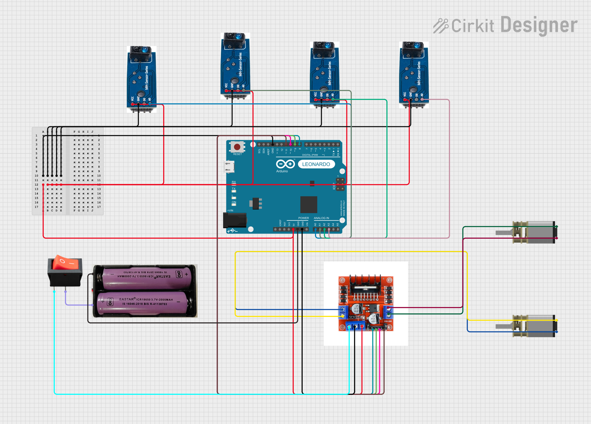

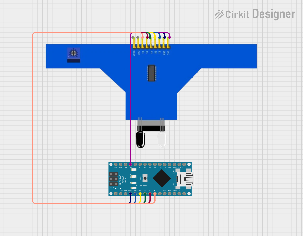

Explore Projects Built with 5 Way IR Line Tracking TCRT5000
Common Applications:
- Line-following robots
- Edge detection for autonomous vehicles
- Obstacle detection in robotics
- Industrial automation for conveyor belt tracking
- Educational projects in electronics and robotics
Technical Specifications
Key Technical Details:
- Operating Voltage: 3.3V to 5V DC
- Output Type: Digital (High/Low) for each sensor
- Detection Range: 1mm to 25mm (optimal at 2mm to 12mm)
- IR Wavelength: 950nm
- Current Consumption: ~10mA per sensor
- Dimensions: 70mm x 12mm x 10mm
- Weight: ~10g
- Operating Temperature: -25°C to 85°C
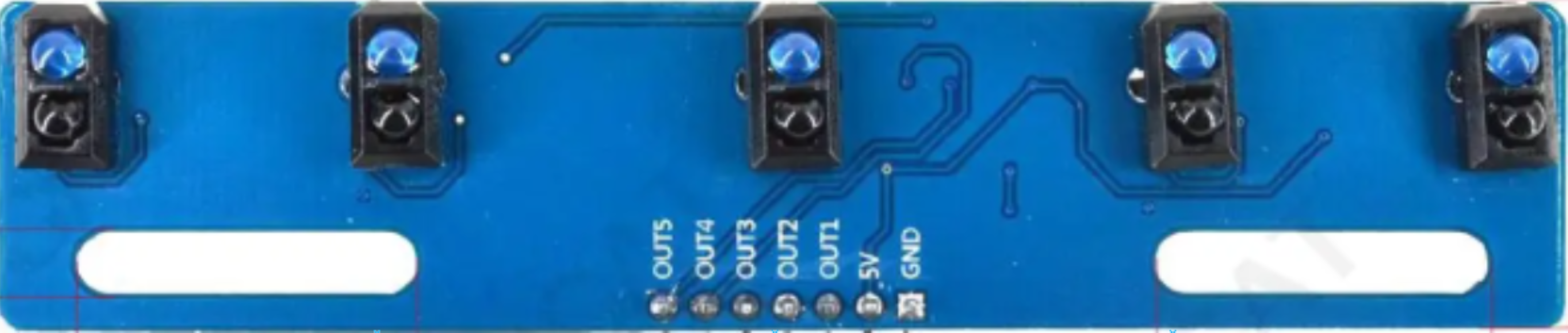
Pin Configuration and Descriptions:
The module has a 7-pin interface for power, ground, and sensor outputs. Below is the pinout:
| Pin | Name | Description |
|---|---|---|
| 1 | VCC | Power supply input (3.3V to 5V DC). |
| 2 | GND | Ground connection. |
| 3 | OUT1 | Digital output of the first sensor (High = no line, Low = line detected). |
| 4 | OUT2 | Digital output of the second sensor (High = no line, Low = line detected). |
| 5 | OUT3 | Digital output of the third sensor (High = no line, Low = line detected). |
| 6 | OUT4 | Digital output of the fourth sensor (High = no line, Low = line detected). |
| 7 | OUT5 | Digital output of the fifth sensor (High = no line, Low = line detected). |
Usage Instructions
How to Use the Component in a Circuit:
Power the Module:
- Connect the VCC pin to a 3.3V or 5V power source.
- Connect the GND pin to the ground of your circuit.
Connect the Outputs:
- Each sensor has a dedicated digital output pin (OUT1 to OUT5). Connect these pins to the digital input pins of your microcontroller (e.g., Arduino UNO).
Position the Module:
- Place the module approximately 2mm to 12mm above the surface to be tracked. Ensure the sensors face the surface directly.
Calibrate the Sensors:
- Test the module on the intended surface to ensure proper detection. Adjust the height or surface contrast if necessary.
Read Sensor Outputs:
- Each sensor outputs a digital signal:
- High (1): No line detected (surface reflects IR light).
- Low (0): Line detected (surface absorbs IR light).
- Each sensor outputs a digital signal:
Important Considerations and Best Practices:
- Surface Contrast: Ensure the line to be tracked has a high contrast with the background (e.g., black line on a white surface).
- Ambient Light: Avoid strong ambient light sources that may interfere with the IR sensors.
- Height Adjustment: Maintain an optimal height (2mm to 12mm) for accurate detection.
- Power Supply: Use a stable power source to avoid fluctuations in sensor readings.
Example Code for Arduino UNO:
Below is an example code snippet to read the outputs of the 5 sensors and display the results in the Serial Monitor:
// Define the pins connected to the sensor outputs
const int sensorPins[5] = {2, 3, 4, 5, 6}; // Digital pins 2 to 6

void setup() {
  // Initialize serial communication for debugging
  Serial.begin(9600);

  // Set sensor pins as inputs
  for (int i = 0; i < 5; i++) {
    pinMode(sensorPins[i], INPUT);
  }
}

void loop() {
  // Read and print the state of each sensor
  Serial.print("Sensor States: ");
  for (int i = 0; i < 5; i++) {
    int sensorState = digitalRead(sensorPins[i]);
    Serial.print(sensorState); // Print 1 (High) or 0 (Low)
    Serial.print(" ");
  }
  Serial.println(); // Move to the next line in the Serial Monitor

  delay(100); // Small delay for readability
}
Troubleshooting and FAQs
Common Issues and Solutions:
Sensors Not Detecting the Line:
- Cause: The module is too far from the surface or the line contrast is insufficient.
- Solution: Adjust the height to 2mm-12mm and ensure the line has a high contrast with the background.
Inconsistent Readings:
- Cause: Ambient light interference or unstable power supply.
- Solution: Shield the module from strong light sources and use a regulated power supply.
All Sensors Output High (1):
- Cause: The module is not positioned over a line or the line is too narrow.
- Solution: Ensure the line is wide enough to be detected by at least one sensor.
All Sensors Output Low (0):
- Cause: The module is positioned over a dark surface or the sensors are dirty.
- Solution: Clean the sensors and test on a surface with proper contrast.
FAQs:
Q1: Can this module detect colors?
A1: No, the TCRT5000 sensors detect surface reflectivity, not color. It works best with high-contrast surfaces.
Q2: Can I use this module with a 3.3V microcontroller?
A2: Yes, the module supports both 3.3V and 5V power supplies.
Q3: How do I connect this module to a motor driver for a line-following robot?
A3: Use the sensor outputs to control the motor driver inputs. For example, if the left sensors detect a line, slow down the left motor to steer the robot back onto the track.
Q4: What is the maximum detection range?
A4: The module can detect lines up to 25mm away, but optimal performance is achieved at 2mm to 12mm.
This concludes the documentation for the 5 Way IR Line Tracking TCRT5000. For further assistance, refer to Arduino's official resources or community forums.