Cirkit Designer Logo
Cirkit Designer
Your all-in-one circuit design IDE
Home / 
Component Documentation

How to Use Arcade Button (white): Examples, Pinouts, and Specs

Image of Arcade Button (white)
Cirkit Designer LogoDesign with Arcade Button (white) in Cirkit Designer

Introduction

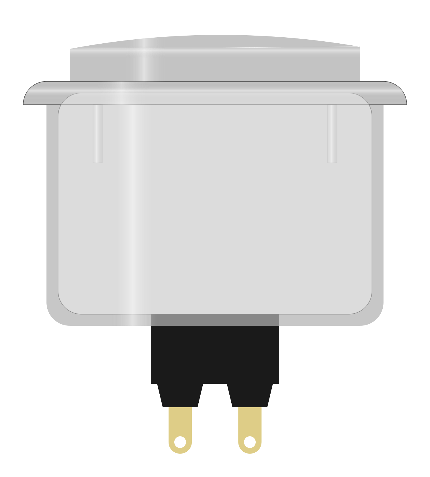
The Arcade Button (White) is a push-button switch commonly used in arcade machines and gaming consoles. It features a durable plastic housing, a white-colored cap, and a spring-loaded mechanism for easy activation. This button provides tactile feedback, making it ideal for user interaction in gaming, industrial control panels, and DIY electronics projects. Its robust design ensures long-lasting performance, even under frequent use.

Explore Projects Built with Arcade Button (white)

Use Cirkit Designer to design, explore, and prototype these projects online. Some projects support real-time simulation. Click "Open Project" to start designing instantly!
Arduino UNO Controlled RGB LED Strip with Interactive Button
Image of Simon Circuit: A project utilizing Arcade Button (white) in a practical application
This circuit features an Arduino UNO connected to a WS2812 RGB LED strip, controlled via digital pin D8. An arcade button is interfaced with the Arduino through a resistor and digital pin D3, likely for user input to control the LED strip. Power is supplied through a 2.1mm DC barrel jack, with an electrolytic capacitor for voltage smoothing, and the ground connections are shared among the components.
Cirkit Designer LogoOpen Project in Cirkit Designer
Arduino Mega 2560-Based Interactive Game with RGB LEDs, LCD Display, and DFPlayer Audio
Image of Game: A project utilizing Arcade Button (white) in a practical application
This circuit is a game controller that uses an Arduino Mega 2560 to manage inputs from multiple arcade buttons, control RGB LEDs, display messages on an LCD, and play audio through a DFPlayer module. The system announces the winner based on button presses, lights up the corresponding RGB LED, and displays the winner's name on the LCD.
Cirkit Designer LogoOpen Project in Cirkit Designer
Arduino-Based Interactive LED Game with I2C LCD Display
Image of test2: A project utilizing Arcade Button (white) in a practical application
This circuit is a simple interactive game system using an Arduino Uno, two WS2812B LEDs, two pushbuttons, and two 16x2 I2C LCDs. The Arduino controls the LEDs and displays game information on the LCDs, while the pushbuttons are used to interact with the game, which involves pressing the correct button based on the LED color displayed.
Cirkit Designer LogoOpen Project in Cirkit Designer
ESP32-Based Interactive LED Game with WS2812B LEDs and OLED Displays
Image of Test: A project utilizing Arcade Button (white) in a practical application
This circuit is a game system controlled by an ESP32 microcontroller, featuring 20 WS2812B LEDs, 10 arcade buttons, and two 128x64 OLED displays. The LEDs are used for visual feedback, the buttons for user input, and the displays for showing game information such as score and time. The system runs a game where players interact with the LEDs and buttons, with the ESP32 managing the game logic and user interface.
Cirkit Designer LogoOpen Project in Cirkit Designer

Explore Projects Built with Arcade Button (white)

Use Cirkit Designer to design, explore, and prototype these projects online. Some projects support real-time simulation. Click "Open Project" to start designing instantly!
Image of Simon Circuit: A project utilizing Arcade Button (white) in a practical application
Arduino UNO Controlled RGB LED Strip with Interactive Button
This circuit features an Arduino UNO connected to a WS2812 RGB LED strip, controlled via digital pin D8. An arcade button is interfaced with the Arduino through a resistor and digital pin D3, likely for user input to control the LED strip. Power is supplied through a 2.1mm DC barrel jack, with an electrolytic capacitor for voltage smoothing, and the ground connections are shared among the components.
Cirkit Designer LogoOpen Project in Cirkit Designer
Image of Game: A project utilizing Arcade Button (white) in a practical application
Arduino Mega 2560-Based Interactive Game with RGB LEDs, LCD Display, and DFPlayer Audio
This circuit is a game controller that uses an Arduino Mega 2560 to manage inputs from multiple arcade buttons, control RGB LEDs, display messages on an LCD, and play audio through a DFPlayer module. The system announces the winner based on button presses, lights up the corresponding RGB LED, and displays the winner's name on the LCD.
Cirkit Designer LogoOpen Project in Cirkit Designer
Image of test2: A project utilizing Arcade Button (white) in a practical application
Arduino-Based Interactive LED Game with I2C LCD Display
This circuit is a simple interactive game system using an Arduino Uno, two WS2812B LEDs, two pushbuttons, and two 16x2 I2C LCDs. The Arduino controls the LEDs and displays game information on the LCDs, while the pushbuttons are used to interact with the game, which involves pressing the correct button based on the LED color displayed.
Cirkit Designer LogoOpen Project in Cirkit Designer
Image of Test: A project utilizing Arcade Button (white) in a practical application
ESP32-Based Interactive LED Game with WS2812B LEDs and OLED Displays
This circuit is a game system controlled by an ESP32 microcontroller, featuring 20 WS2812B LEDs, 10 arcade buttons, and two 128x64 OLED displays. The LEDs are used for visual feedback, the buttons for user input, and the displays for showing game information such as score and time. The system runs a game where players interact with the LEDs and buttons, with the ESP32 managing the game logic and user interface.
Cirkit Designer LogoOpen Project in Cirkit Designer

Common Applications:

  • Arcade gaming machines
  • DIY gaming controllers
  • Industrial control panels
  • Interactive kiosks
  • Educational electronics projects

Technical Specifications

Below are the key technical details of the Arcade Button (White):

Parameter Value
Button Type Momentary push-button
Actuation Force ~50g
Housing Material Durable plastic
Cap Color White
Contact Rating 12V DC, 1A
Mounting Hole Diameter 28mm
Terminal Type Solder lugs
Lifespan ~1,000,000 cycles

Pin Configuration and Descriptions

The Arcade Button (White) typically has two solder lug terminals for electrical connections:

Pin Description
Pin 1 Connects to the positive side of the circuit
Pin 2 Connects to the ground or negative side

Usage Instructions

How to Use the Arcade Button in a Circuit

  1. Mounting the Button: Drill a 28mm hole in your panel or enclosure. Insert the button into the hole and secure it using the provided mounting nut.
  2. Wiring the Button:
    • Solder one terminal (Pin 1) to the positive side of your circuit or microcontroller input pin.
    • Solder the other terminal (Pin 2) to the ground or negative side of the circuit.
  3. Testing the Button: Once connected, pressing the button will momentarily close the circuit, allowing current to flow.

Important Considerations and Best Practices

  • Debouncing: Mechanical buttons like this one may produce noise or "bouncing" when pressed. Use a hardware or software debounce mechanism to ensure reliable operation.
  • Voltage and Current Ratings: Do not exceed the rated 12V DC and 1A to avoid damaging the button.
  • Secure Connections: Ensure solder joints are strong and insulated to prevent short circuits.
  • Mounting: Avoid overtightening the mounting nut, as it may damage the plastic housing.

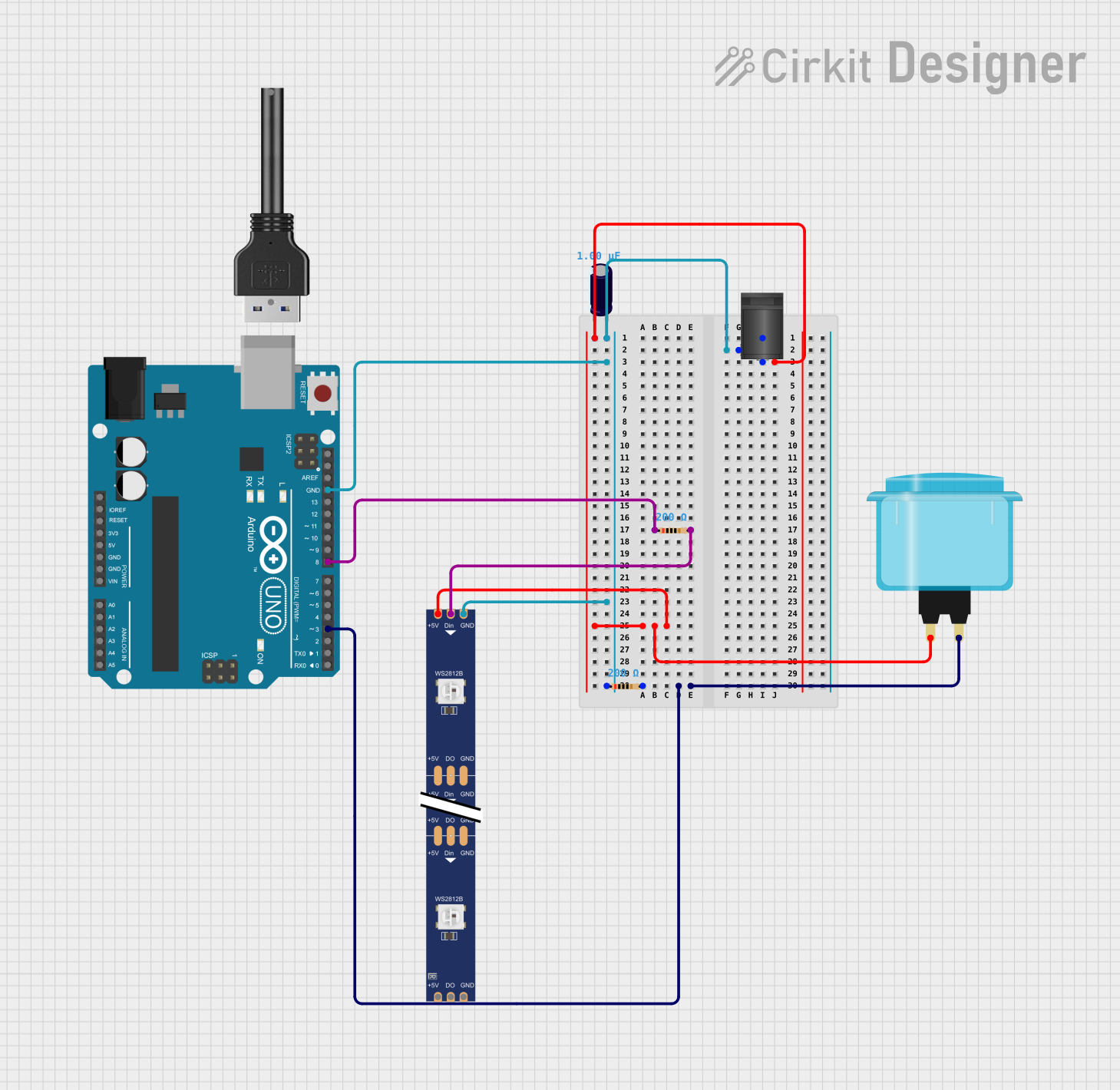
Example: Connecting to an Arduino UNO

The Arcade Button (White) can be easily interfaced with an Arduino UNO for interactive projects. Below is an example of how to connect and program the button:

Circuit Diagram

  • Connect Pin 1 of the button to Arduino digital pin 2.
  • Connect Pin 2 of the button to the Arduino GND pin.
  • Use a 10kΩ pull-down resistor between digital pin 2 and GND to ensure a stable LOW state when the button is not pressed.

Arduino Code

// Arcade Button Example with Arduino UNO
// This code reads the state of the button and turns on an LED when pressed.

const int buttonPin = 2;  // Pin connected to the button
const int ledPin = 13;    // Pin connected to the onboard LED

void setup() {
  pinMode(buttonPin, INPUT);  // Set button pin as input
  pinMode(ledPin, OUTPUT);   // Set LED pin as output
  digitalWrite(ledPin, LOW); // Ensure LED is off initially
}

void loop() {
  int buttonState = digitalRead(buttonPin); // Read the button state

  if (buttonState == HIGH) {
    // If button is pressed, turn on the LED
    digitalWrite(ledPin, HIGH);
  } else {
    // If button is not pressed, turn off the LED
    digitalWrite(ledPin, LOW);
  }
}

Troubleshooting and FAQs

Common Issues and Solutions

  1. Button Not Responding:

    • Cause: Loose or incorrect wiring.
    • Solution: Check all connections and ensure the solder joints are secure.
  2. Button Bounces or Produces Erratic Behavior:

    • Cause: Mechanical bouncing of the button contacts.
    • Solution: Implement a debounce circuit or software debounce in your code.
  3. Button Feels Stiff or Stuck:

    • Cause: Dirt or debris inside the button mechanism.
    • Solution: Clean the button with compressed air or a soft brush.
  4. Button Exceeds Voltage/Current Ratings:

    • Cause: Using the button in a high-power circuit.
    • Solution: Use a relay or transistor to handle higher voltages or currents.

FAQs

Q: Can I use this button with a Raspberry Pi?
A: Yes, the Arcade Button (White) can be used with a Raspberry Pi. Connect it to a GPIO pin and use a pull-up or pull-down resistor for stable operation.

Q: Is the button waterproof?
A: No, the Arcade Button (White) is not waterproof. Avoid using it in environments with high moisture or water exposure.

Q: Can I replace the white cap with a different color?
A: Yes, the cap is removable and can be replaced with compatible caps of different colors.

Q: How do I debounce the button in software?
A: You can use a simple delay or a debounce library in your code to filter out noise caused by mechanical bouncing.