
How to Use SparkFun RPI-1031 Tilt-a-Whirl Breakout: Examples, Pinouts, and Specs
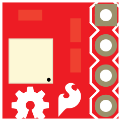
 Design with SparkFun RPI-1031 Tilt-a-Whirl Breakout in Cirkit Designer
Introduction
The SparkFun RPI-1031 Tilt-a-Whirl Breakout is a compact and versatile breakout board designed for the Raspberry Pi. It simplifies the integration of tilt sensors into your projects, enabling precise tilt detection and orientation sensing. This breakout board is ideal for applications such as motion detection, robotics, gaming controllers, and other projects requiring tilt-based input.
With its user-friendly design, the RPI-1031 is perfect for both beginners and experienced developers looking to add tilt functionality to their Raspberry Pi-based systems.
Explore Projects Built with SparkFun RPI-1031 Tilt-a-Whirl Breakout
 Open Project in Cirkit Designer
 Open Project in Cirkit Designer
 Open Project in Cirkit Designer
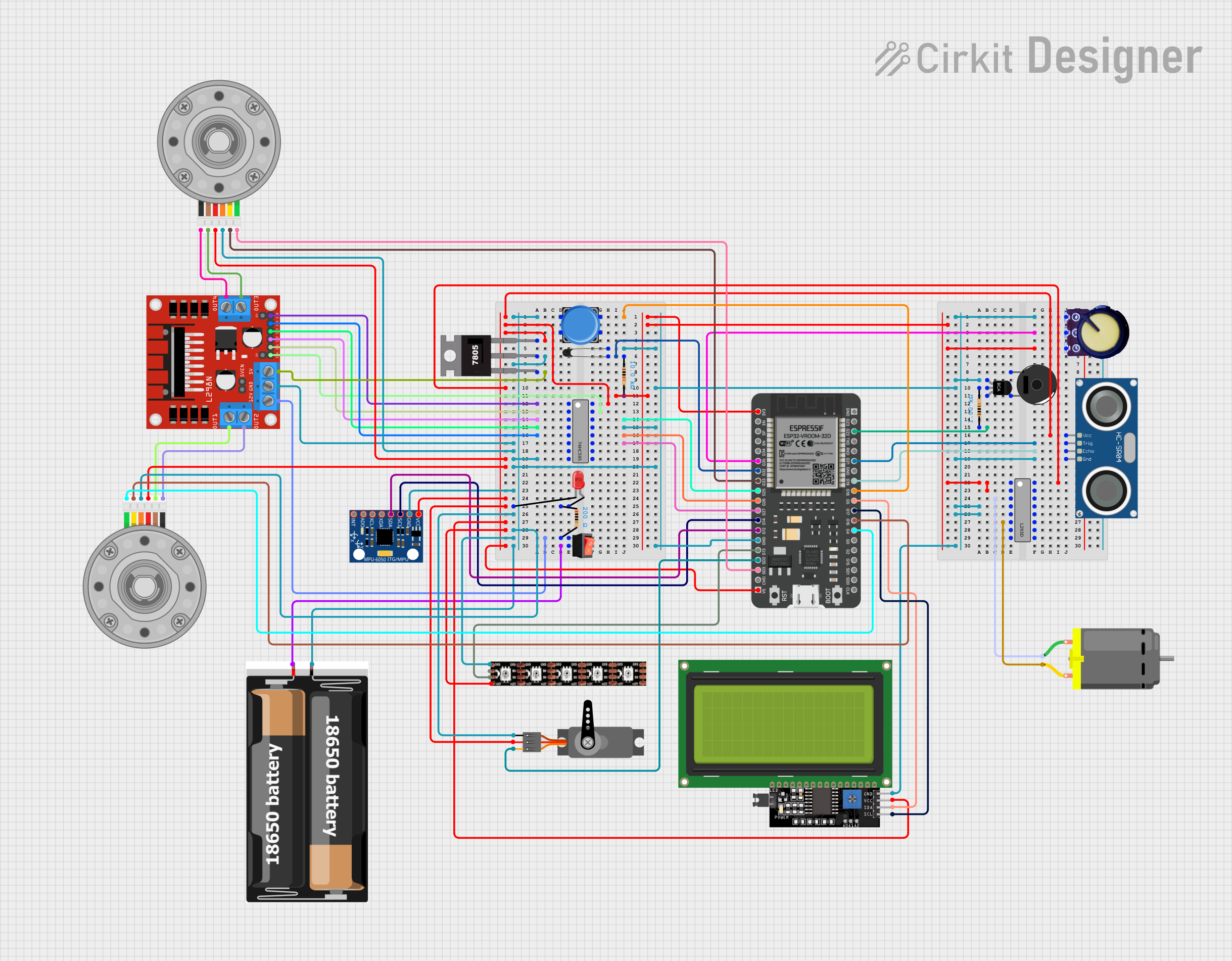 Open Project in Cirkit Designer
Explore Projects Built with SparkFun RPI-1031 Tilt-a-Whirl Breakout
Open Project in Cirkit DesignerOpen Project in Cirkit DesignerOpen Project in Cirkit DesignerOpen Project in Cirkit DesignerCommon Applications and Use Cases
- Motion detection in robotics
- Gaming controllers with tilt-based input
- Orientation sensing in IoT devices
- Wearable technology
- Educational projects for learning about tilt sensors
Technical Specifications
Key Technical Details
- Manufacturer: SparkFun
- Part ID: RPI-1031
- Input Voltage: 3.3V (compatible with Raspberry Pi GPIO)
- Output Type: Digital (High/Low based on tilt state)
- Tilt Sensor Type: Ball-in-cage tilt switch
- Dimensions: 25mm x 25mm (1" x 1")
- Mounting Holes: 2x M2.5 for secure attachment
- Operating Temperature: -10°C to 50°C
Pin Configuration and Descriptions
The RPI-1031 breakout board has a simple 3-pin interface for easy connection to the Raspberry Pi or other microcontrollers.
| Pin | Name | Description |
|---|---|---|
| 1 | VCC | Power input (3.3V). Connect to the 3.3V pin on the Raspberry Pi. |
| 2 | GND | Ground. Connect to the GND pin on the Raspberry Pi. |
| 3 | OUT | Digital output. Outputs HIGH (3.3V) when tilted and LOW (0V) when level. |
Usage Instructions
How to Use the Component in a Circuit
Connect the Pins:
- Connect the
VCCpin of the RPI-1031 to the 3.3V pin on the Raspberry Pi. - Connect the
GNDpin to a ground pin on the Raspberry Pi. - Connect the
OUTpin to a GPIO pin on the Raspberry Pi (e.g., GPIO17).
- Connect the
Mount the Breakout Board:
Secure the breakout board using the mounting holes to ensure stable operation.Read the Output:
TheOUTpin will output a HIGH signal (3.3V) when the tilt sensor is activated (tilted) and a LOW signal (0V) when the sensor is level.
Important Considerations and Best Practices
- Voltage Compatibility: Ensure the breakout board is powered with 3.3V to avoid damage.
- Debouncing: The tilt sensor may produce noisy signals due to mechanical bouncing. Use software debouncing techniques to filter out false triggers.
- Orientation: The tilt sensor's sensitivity depends on its orientation. Test and adjust the mounting angle for optimal performance.
- Avoid Vibration: Excessive vibration may cause erratic behavior. Use vibration-dampening materials if necessary.
Example Code for Raspberry Pi (Python)
Below is an example Python script to read the tilt sensor's output using the Raspberry Pi's GPIO pins.
import RPi.GPIO as GPIO
import time
Pin configuration
TILT_SENSOR_PIN = 17 # GPIO pin connected to the OUT pin of the RPI-1031
GPIO setup
GPIO.setmode(GPIO.BCM) # Use BCM pin numbering GPIO.setup(TILT_SENSOR_PIN, GPIO.IN) # Set the pin as an input
print("Tilt Sensor Test - Press Ctrl+C to exit")
try: while True: if GPIO.input(TILT_SENSOR_PIN): # Check if the sensor is tilted print("Tilt detected!") else: print("Sensor is level.") time.sleep(0.1) # Small delay to reduce CPU usage except KeyboardInterrupt: print("Exiting program.") finally: GPIO.cleanup() # Reset GPIO settings
---
Troubleshooting and FAQs
Common Issues and Solutions
No Output Signal:
- Cause: Incorrect wiring or loose connections.
- Solution: Double-check the wiring and ensure all connections are secure.
Erratic Behavior:
- Cause: Mechanical bouncing or excessive vibration.
- Solution: Implement software debouncing in your code and minimize vibrations.
Sensor Always HIGH or LOW:
- Cause: Faulty tilt sensor or incorrect orientation.
- Solution: Test the sensor with a multimeter and adjust its orientation.
GPIO Pin Not Responding:
- Cause: GPIO pin not configured correctly in the code.
- Solution: Verify the GPIO pin number in the script and ensure it matches your wiring.
FAQs
Q: Can I use the RPI-1031 with a 5V microcontroller?
A: The RPI-1031 is designed for 3.3V operation. Using it with a 5V microcontroller may damage the board. Use a level shifter if necessary.
Q: How do I debounce the tilt sensor signal?
A: You can implement software debouncing by adding a small delay (e.g., 50ms) after detecting a tilt event to filter out noise.
Q: Can I use multiple RPI-1031 boards in one project?
A: Yes, you can connect multiple boards to different GPIO pins on the Raspberry Pi. Ensure each board has its own unique GPIO connection.
Q: Is the RPI-1031 compatible with Arduino?
A: While designed for the Raspberry Pi, the RPI-1031 can be used with Arduino boards that operate at 3.3V. Connect the pins accordingly and use digital input functions to read the sensor's output.
This concludes the documentation for the SparkFun RPI-1031 Tilt-a-Whirl Breakout. For additional support, visit the SparkFun website.