Cirkit Designer Logo
Cirkit Designer
Your all-in-one circuit design IDE
Home / 
Component Documentation

How to Use AS7341: Examples, Pinouts, and Specs

Image of AS7341
Cirkit Designer LogoDesign with AS7341 in Cirkit Designer

Introduction

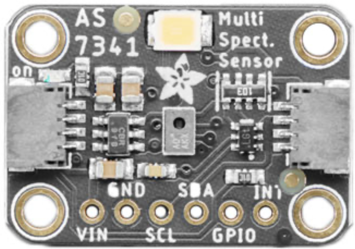
The AS7341 is a highly versatile spectral sensor manufactured by Adafruit. It is designed to measure light intensity across multiple wavelengths, making it ideal for applications requiring precise color and light analysis. The sensor features 11 channels for color detection, enabling advanced optical measurements in a compact form factor.

Explore Projects Built with AS7341

Use Cirkit Designer to design, explore, and prototype these projects online. Some projects support real-time simulation. Click "Open Project" to start designing instantly!
Satellite-Based Timing and Navigation System with SDR and Atomic Clock Synchronization
Image of GPS 시스템 측정 구성도_Confirm: A project utilizing AS7341 in a practical application
This circuit appears to be a complex system involving power supply management, GPS and timing synchronization, and data communication. It includes a SI-TEX G1 Satellite Compass for GPS data, an XHTF1021 Atomic Rubidium Clock for precise timing, and Ettus USRP B200 units for software-defined radio communication. Power is supplied through various SMPS units and distributed via terminal blocks and DC jacks. Data communication is facilitated by Beelink MINI S12 N95 computers, RS232 splitters, and a 1000BASE-T Media Converter for network connectivity. RF Directional Couplers are used to interface antennas with the USRP units, and the entire system is likely contained within cases for protection and organization.
Cirkit Designer LogoOpen Project in Cirkit Designer
Battery-Powered Emergency Alert System with NUCLEO-F072RB, SIM800L, and GPS NEO 6M
Image of women safety: A project utilizing AS7341 in a practical application
This circuit is an emergency alert system that uses a NUCLEO-F072RB microcontroller to send SMS alerts and make calls via a SIM800L GSM module, while obtaining location data from a GPS NEO 6M module. The system is powered by a Li-ion battery and includes a TP4056 module for battery charging and protection, with a rocker switch to control power to the microcontroller.
Cirkit Designer LogoOpen Project in Cirkit Designer
Logic Gate Circuit with 7408 AND and 7432 OR ICs
Image of gate: A project utilizing AS7341 in a practical application
This circuit includes a 7408 AND gate IC and a 7432 OR gate IC, both powered by a common VCC and GND connection. The circuit is designed to perform basic logical operations, combining AND and OR gates for digital signal processing.
Cirkit Designer LogoOpen Project in Cirkit Designer
Cellular-Enabled IoT Device with Real-Time Clock and Power Management
Image of LRCM PHASE 2 BASIC: A project utilizing AS7341 in a practical application
This circuit features a LilyGo-SIM7000G module for cellular communication and GPS functionality, interfaced with an RTC DS3231 for real-time clock capabilities. It includes voltage sensing through two voltage sensor modules, and uses an 8-channel opto-coupler for isolating different parts of the circuit. Power management is handled by a buck converter connected to a DC power source and batteries, with a fuse for protection and a rocker switch for on/off control. Additionally, there's an LED for indication purposes.
Cirkit Designer LogoOpen Project in Cirkit Designer

Explore Projects Built with AS7341

Use Cirkit Designer to design, explore, and prototype these projects online. Some projects support real-time simulation. Click "Open Project" to start designing instantly!
Image of GPS 시스템 측정 구성도_Confirm: A project utilizing AS7341 in a practical application
Satellite-Based Timing and Navigation System with SDR and Atomic Clock Synchronization
This circuit appears to be a complex system involving power supply management, GPS and timing synchronization, and data communication. It includes a SI-TEX G1 Satellite Compass for GPS data, an XHTF1021 Atomic Rubidium Clock for precise timing, and Ettus USRP B200 units for software-defined radio communication. Power is supplied through various SMPS units and distributed via terminal blocks and DC jacks. Data communication is facilitated by Beelink MINI S12 N95 computers, RS232 splitters, and a 1000BASE-T Media Converter for network connectivity. RF Directional Couplers are used to interface antennas with the USRP units, and the entire system is likely contained within cases for protection and organization.
Cirkit Designer LogoOpen Project in Cirkit Designer
Image of women safety: A project utilizing AS7341 in a practical application
Battery-Powered Emergency Alert System with NUCLEO-F072RB, SIM800L, and GPS NEO 6M
This circuit is an emergency alert system that uses a NUCLEO-F072RB microcontroller to send SMS alerts and make calls via a SIM800L GSM module, while obtaining location data from a GPS NEO 6M module. The system is powered by a Li-ion battery and includes a TP4056 module for battery charging and protection, with a rocker switch to control power to the microcontroller.
Cirkit Designer LogoOpen Project in Cirkit Designer
Image of gate: A project utilizing AS7341 in a practical application
Logic Gate Circuit with 7408 AND and 7432 OR ICs
This circuit includes a 7408 AND gate IC and a 7432 OR gate IC, both powered by a common VCC and GND connection. The circuit is designed to perform basic logical operations, combining AND and OR gates for digital signal processing.
Cirkit Designer LogoOpen Project in Cirkit Designer
Image of LRCM PHASE 2 BASIC: A project utilizing AS7341 in a practical application
Cellular-Enabled IoT Device with Real-Time Clock and Power Management
This circuit features a LilyGo-SIM7000G module for cellular communication and GPS functionality, interfaced with an RTC DS3231 for real-time clock capabilities. It includes voltage sensing through two voltage sensor modules, and uses an 8-channel opto-coupler for isolating different parts of the circuit. Power management is handled by a buck converter connected to a DC power source and batteries, with a fuse for protection and a rocker switch for on/off control. Additionally, there's an LED for indication purposes.
Cirkit Designer LogoOpen Project in Cirkit Designer

Common Applications and Use Cases

  • Color sensing: Detect and analyze colors in various environments.
  • Ambient light sensing: Measure light intensity for smart lighting systems.
  • Agriculture: Monitor plant health by analyzing light absorption and reflection.
  • Display calibration: Ensure accurate color reproduction in screens and monitors.
  • Scientific research: Perform spectral analysis for experiments and studies.

Technical Specifications

The AS7341 is a powerful and compact spectral sensor with the following key specifications:

Parameter Value
Operating Voltage 3.3V (logic level)
Communication Interface I²C (up to 1 MHz)
Spectral Channels 11 (visible and near-infrared wavelengths)
Spectral Range 350 nm to 1000 nm
Operating Temperature -40°C to +85°C
Power Consumption 0.7 mA (typical)
Package Dimensions 2.0 mm x 2.0 mm x 0.75 mm

Pin Configuration and Descriptions

The AS7341 sensor is typically available on a breakout board from Adafruit. Below is the pinout for the breakout board:

Pin Name Description
VIN Power input (3.3V or 5V). Provides power to the sensor.
GND Ground connection.
SDA I²C data line. Used for communication with a microcontroller.
SCL I²C clock line. Used for communication with a microcontroller.
INT Interrupt pin. Can be used to signal the microcontroller when data is ready.
LDR LED driver pin. Can control an external light source for measurements.

Usage Instructions

How to Use the AS7341 in a Circuit

  1. Power the Sensor: Connect the VIN pin to a 3.3V or 5V power source and the GND pin to ground.
  2. Connect I²C Lines: Connect the SDA and SCL pins to the corresponding I²C pins on your microcontroller.
  3. Optional Connections:
    • Use the INT pin to receive interrupts from the sensor.
    • Connect the LDR pin to an external LED if additional illumination is required.
  4. Install Required Libraries: If using an Arduino, install the Adafruit AS7341 library via the Arduino Library Manager.

Important Considerations and Best Practices

  • Voltage Levels: Ensure the I²C lines are at 3.3V logic levels. Use a level shifter if your microcontroller operates at 5V.
  • Illumination: For accurate measurements, use a consistent and stable light source. The LDR pin can help control an external LED.
  • I²C Address: The default I²C address for the AS7341 is 0x39. Ensure no other devices on the I²C bus share this address.
  • Calibration: For precise color measurements, calibrate the sensor in your specific environment.

Example Code for Arduino UNO

Below is an example of how to use the AS7341 with an Arduino UNO:

#include <Wire.h>
#include "Adafruit_AS7341.h"

// Create an instance of the AS7341 sensor
Adafruit_AS7341 as7341;

void setup() {
  Serial.begin(115200); // Initialize serial communication
  while (!Serial);      // Wait for the serial monitor to open

  // Initialize I²C communication and the AS7341 sensor
  if (!as7341.begin()) {
    Serial.println("Failed to initialize AS7341 sensor!");
    while (1); // Halt execution if initialization fails
  }

  Serial.println("AS7341 sensor initialized successfully!");
}

void loop() {
  // Read and print the light intensity for all 11 channels
  for (int i = 0; i < 11; i++) {
    uint16_t channelData = as7341.readChannel(i);
    Serial.print("Channel ");
    Serial.print(i);
    Serial.print(": ");
    Serial.println(channelData);
  }

  delay(1000); // Wait 1 second before the next reading
}

Troubleshooting and FAQs

Common Issues and Solutions

  1. Sensor Not Detected on I²C Bus:

    • Ensure the SDA and SCL lines are correctly connected to the microcontroller.
    • Verify the I²C address (0x39) and check for conflicts with other devices.
    • Use pull-up resistors (typically 4.7 kΩ) on the SDA and SCL lines if not already present.
  2. Inaccurate Measurements:

    • Ensure the sensor is not exposed to direct sunlight or other extreme lighting conditions.
    • Use a stable and consistent light source for measurements.
    • Perform calibration in the specific environment where the sensor will be used.
  3. Interrupt Pin Not Working:

    • Verify that the INT pin is correctly connected to a digital input pin on the microcontroller.
    • Check the sensor's configuration to ensure interrupts are enabled.

FAQs

Q: Can the AS7341 measure UV or infrared light?
A: The AS7341 primarily measures visible and near-infrared light, with a spectral range of 350 nm to 1000 nm. It does not measure UV light.

Q: What is the maximum I²C speed supported by the AS7341?
A: The AS7341 supports I²C communication speeds of up to 1 MHz (Fast Mode Plus).

Q: Can I use the AS7341 with a 5V microcontroller?
A: Yes, but you must use a level shifter to convert the 5V logic levels to 3.3V for the I²C lines.

Q: How do I control an external LED with the LDR pin?
A: The LDR pin can be connected to the control input of an LED driver circuit. Refer to the Adafruit AS7341 library for examples of how to configure the LDR pin.

This concludes the documentation for the AS7341 spectral sensor. For further assistance, refer to the Adafruit product page or community forums.