How to Use Toggle Switch spst: Examples, Pinouts, and Specs
Introduction
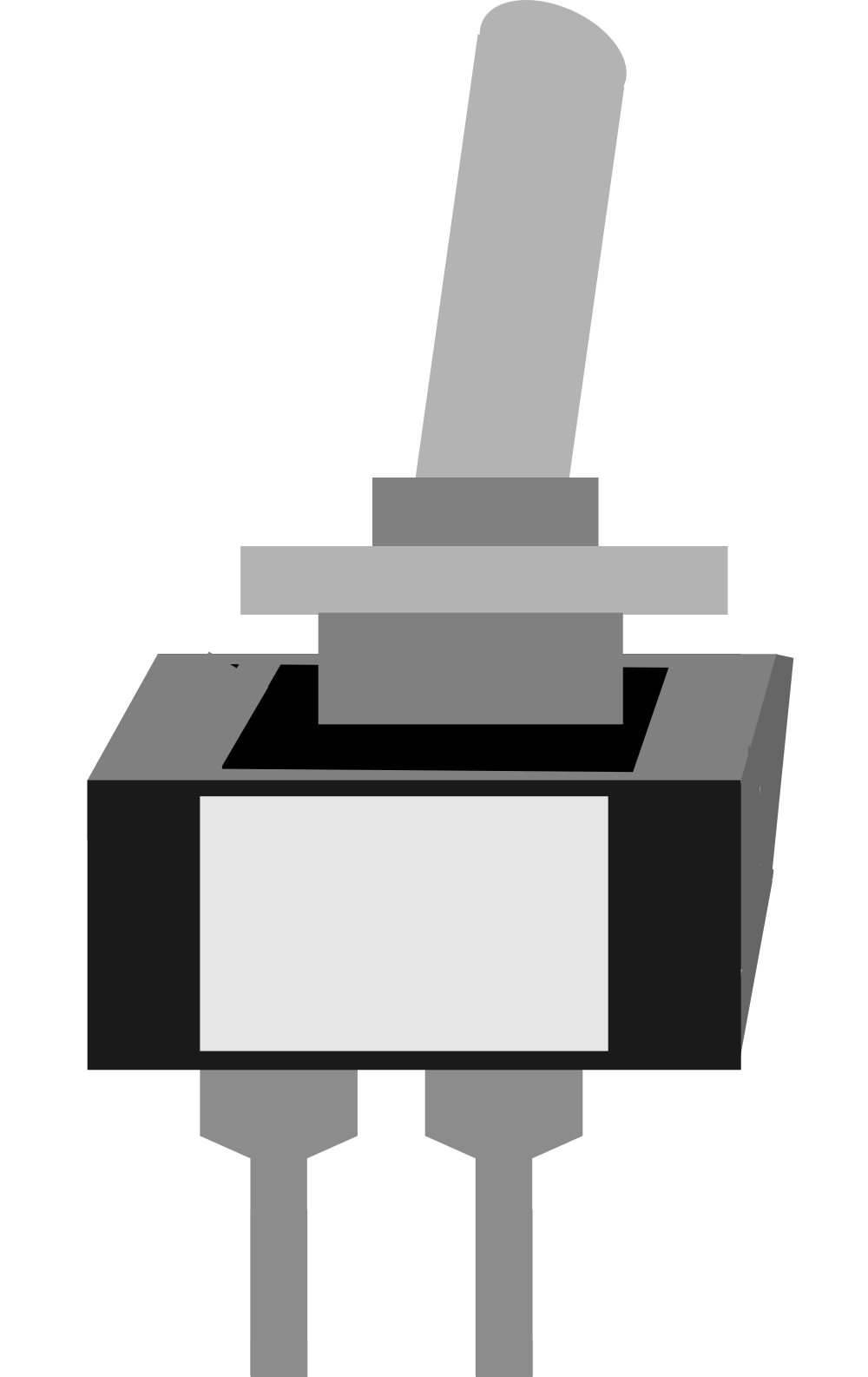
A Single Pole Single Throw (SPST) toggle switch is a simple yet essential component in electronics. It operates as a binary device, with two positions: ON and OFF. This type of switch controls a single circuit, making or breaking the connection with a single action. SPST toggle switches are widely used in household appliances, industrial equipment, and hobby electronics for controlling power or as a user interface component.
Explore Projects Built with Toggle Switch spst
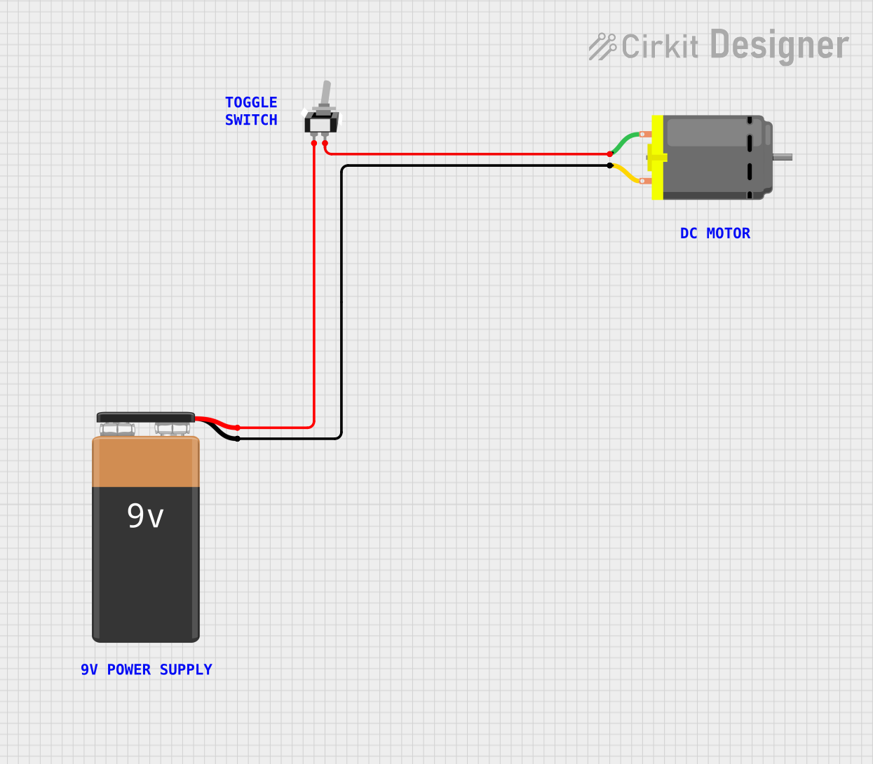


Explore Projects Built with Toggle Switch spst
Common Applications and Use Cases
- Power switches for devices
- Light controls
- Simple on/off control for circuits
- User input for hobby projects, such as robotics or Arduino-based systems
Technical Specifications
Key Technical Details
- Voltage Rating: Typically ranges from 120V to 250V AC
- Current Rating: Commonly rated for 2A to 20A at the maximum voltage
- Contact Resistance: Usually less than 20 mΩ
- Insulation Resistance: Typically greater than 100 MΩ
- Dielectric Strength: Often withstands 1000V AC for 1 minute
- Operating Temperature: Ranges from -30°C to 85°C
Pin Configuration and Descriptions
| Pin Number | Description |
|---|---|
| 1 | Common terminal (C) |
| 2 | Normally Open (NO) |
- Common (C): The fixed part of the switch to which the moving part makes or breaks the connection.
- Normally Open (NO): The contact that is connected to the common terminal when the switch is in the ON position.
Usage Instructions
How to Use the Component in a Circuit
- Identify the Pins: Locate the common (C) and normally open (NO) terminals on the switch.
- Circuit Integration: Connect the common terminal to one side of the power source or the component to be controlled.
- Load Connection: Attach the normally open terminal to the other side of the load (e.g., a light bulb, motor, etc.).
- Mounting: Secure the toggle switch to your project enclosure or panel.
- Operation: Flip the lever to the ON position to close the circuit and power the load. Flip it back to the OFF position to open the circuit and stop the power flow.
Important Considerations and Best Practices
- Ensure the switch's voltage and current ratings are suitable for your application.
- Use a switch with a higher rating than the maximum expected load to ensure reliability and safety.
- If used in a DC circuit, be aware that DC ratings are often lower than AC ratings for the same switch.
- For high-power applications, consider using a switch with a built-in safety cover to prevent accidental actuation.
- Always disconnect power before installing or servicing the switch.
Troubleshooting and FAQs
Common Issues
- Switch Does Not Operate: Check if the switch is properly mounted and the terminals are securely connected.
- Intermittent Connection: Inspect for loose connections or damage to the switch terminals.
- Overheating: Ensure the current through the switch does not exceed its rated capacity.
Solutions and Tips for Troubleshooting
- Verify that the switch is correctly wired to the circuit.
- Tighten any loose connections and replace damaged components.
- If the switch is rated for AC, do not use it in a DC circuit without confirming its DC rating.
- Use a multimeter to check for continuity when the switch is in the ON position.
FAQs
Q: Can I use this switch with a DC power supply? A: Yes, but ensure the DC voltage and current do not exceed the switch's ratings.
Q: What does SPST mean? A: SPST stands for Single Pole Single Throw, indicating the switch controls one circuit and has two positions.
Q: Is it possible to use the switch with an Arduino? A: Absolutely. The switch can serve as a simple digital input for an Arduino.
Example Arduino Code
// Define the pin connected to the toggle switch
const int toggleSwitchPin = 2;

void setup() {
  // Set the toggle switch pin as an input
  pinMode(toggleSwitchPin, INPUT);
  // Initialize serial communication at 9600 bits per second
  Serial.begin(9600);
}

void loop() {
  // Read the state of the toggle switch
  int switchState = digitalRead(toggleSwitchPin);

  // Print the state of the switch to the Serial Monitor
  Serial.println(switchState);
  delay(500); // Delay for half a second
}
Note: In this example, the common terminal of the switch should be connected to the GND pin on the Arduino, and the normally open terminal to digital pin 2. When the switch is in the ON position, the digital pin reads LOW due to the pull-up resistor enabled by default on the input pins.