
How to Use NAU7802 Load Cell ADC: Examples, Pinouts, and Specs
 Design with NAU7802 Load Cell ADC in Cirkit Designer
Introduction
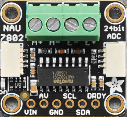
The NAU7802 is a high-precision analog-to-digital converter (ADC) designed specifically for load cell applications. It features a 24-bit resolution and a built-in programmable gain amplifier (PGA), making it ideal for applications requiring accurate weight measurements. The device communicates via the I2C protocol, ensuring seamless integration with microcontroller-based systems. Its low power consumption and high accuracy make it suitable for battery-powered devices, industrial scales, and IoT-based weighing systems.
Explore Projects Built with NAU7802 Load Cell ADC
 Open Project in Cirkit Designer
 Open Project in Cirkit Designer
 Open Project in Cirkit Designer
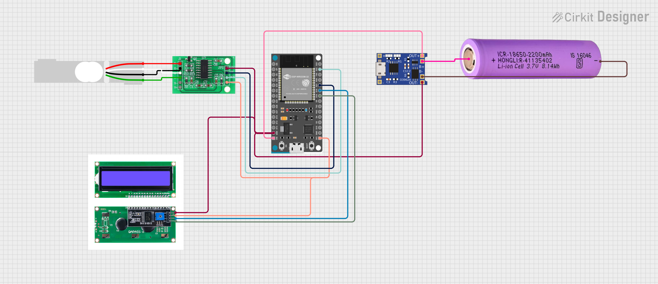 Open Project in Cirkit Designer
Explore Projects Built with NAU7802 Load Cell ADC
Open Project in Cirkit DesignerOpen Project in Cirkit DesignerOpen Project in Cirkit DesignerOpen Project in Cirkit DesignerCommon Applications
- Digital weighing scales
- Industrial load measurement systems
- IoT-based weight monitoring
- Portable weighing devices
- Force measurement in robotics
Technical Specifications
Key Technical Details
| Parameter | Value |
|---|---|
| Resolution | 24-bit |
| Input Voltage Range | ±0.5V (differential) |
| Supply Voltage | 2.7V to 5.5V |
| Programmable Gain | 1, 2, 4, 8, 16, 32, 64, 128 |
| Communication Interface | I2C |
| Operating Temperature | -40°C to +85°C |
| Current Consumption | 1.2mA (typical) |
| Output Data Rate | 10Hz to 320Hz |
Pin Configuration and Descriptions
The NAU7802 is typically available in a 16-pin QFN package. Below is the pin configuration:
| Pin No. | Pin Name | Description |
|---|---|---|
| 1 | AVDD | Analog power supply (2.7V to 5.5V) |
| 2 | AVSS | Analog ground |
| 3 | VREFP | Positive reference voltage input |
| 4 | VREFN | Negative reference voltage input |
| 5 | VINP | Positive analog input (differential input) |
| 6 | VINN | Negative analog input (differential input) |
| 7 | CAP | External capacitor connection for internal voltage regulator |
| 8 | DVDD | Digital power supply (2.7V to 5.5V) |
| 9 | DVSS | Digital ground |
| 10 | SDA | I2C data line |
| 11 | SCL | I2C clock line |
| 12 | DRDY | Data ready output (active low) |
| 13 | CS | Chip select (active low, used in SPI mode; tie high for I2C mode) |
| 14 | RESET | Reset input (active low) |
| 15 | XTAL1 | Crystal oscillator input |
| 16 | XTAL2 | Crystal oscillator output |
Usage Instructions
How to Use the NAU7802 in a Circuit
- Power Supply: Connect AVDD and DVDD to a stable power source (2.7V to 5.5V). Connect AVSS and DVSS to ground.
- Load Cell Connection: Connect the load cell's differential output to VINP and VINN. Ensure proper shielding to minimize noise.
- Reference Voltage: Provide a stable reference voltage to VREFP and VREFN. Typically, AVDD and AVSS can be used as references.
- I2C Communication: Connect the SDA and SCL pins to the corresponding I2C pins on your microcontroller. Use pull-up resistors (typically 4.7kΩ) on both lines.
- External Capacitor: Connect a capacitor (e.g., 1µF) to the CAP pin for the internal voltage regulator.
- Crystal Oscillator: If required, connect a crystal oscillator to XTAL1 and XTAL2 for clock generation.
Important Considerations
- Use decoupling capacitors (e.g., 0.1µF) near the power supply pins to reduce noise.
- Ensure proper grounding to avoid measurement errors.
- Configure the programmable gain amplifier (PGA) based on the load cell's output range.
- Use shielded cables for the load cell to minimize electromagnetic interference (EMI).
Example Code for Arduino UNO
Below is an example of how to interface the NAU7802 with an Arduino UNO using the I2C protocol:
#include <Wire.h>

// NAU7802 I2C address
#define NAU7802_ADDRESS 0x2A

// Register addresses
#define NAU7802_PU_CTRL 0x00
#define NAU7802_CTRL1   0x01
#define NAU7802_CTRL2   0x02
#define NAU7802_ADCO_B2 0x12 // ADC output MSB

void setup() {
  Wire.begin(); // Initialize I2C communication
  Serial.begin(9600); // Initialize serial communication for debugging

  // Power up the NAU7802
  Wire.beginTransmission(NAU7802_ADDRESS);
  Wire.write(NAU7802_PU_CTRL);
  Wire.write(0x30); // Enable power-up and oscillator
  Wire.endTransmission();
  delay(10); // Wait for the device to stabilize

  // Configure the gain (e.g., gain = 128)
  Wire.beginTransmission(NAU7802_ADDRESS);
  Wire.write(NAU7802_CTRL1);
  Wire.write(0x07); // Set gain to 128
  Wire.endTransmission();
}

void loop() {
  // Read ADC data
  Wire.beginTransmission(NAU7802_ADDRESS);
  Wire.write(NAU7802_ADCO_B2); // Start reading from ADC output MSB
  Wire.endTransmission(false);
  Wire.requestFrom(NAU7802_ADDRESS, 3); // Request 3 bytes (MSB, Mid, LSB)

  if (Wire.available() == 3) {
    long adcValue = 0;
    adcValue |= (long)Wire.read() << 16; // MSB
    adcValue |= (long)Wire.read() << 8;  // Mid
    adcValue |= (long)Wire.read();       // LSB

    // Convert to signed 24-bit value
    if (adcValue & 0x800000) {
      adcValue |= 0xFF000000; // Sign extend if negative
    }

    Serial.println(adcValue); // Print ADC value
  }

  delay(500); // Wait before the next reading
}
Troubleshooting and FAQs
Common Issues and Solutions
No Communication with the NAU7802
- Ensure the I2C pull-up resistors (4.7kΩ) are connected to SDA and SCL.
- Verify the I2C address (default is 0x2A) and ensure no address conflicts on the bus.
- Check the wiring for loose or incorrect connections.
Unstable or Noisy Readings
- Use shielded cables for the load cell to reduce EMI.
- Add decoupling capacitors near the power supply pins.
- Ensure the reference voltage is stable and noise-free.
Incorrect ADC Values
- Verify the load cell connections (VINP and VINN).
- Check the PGA gain setting and ensure it matches the load cell's output range.
- Confirm that the load cell is properly calibrated.
FAQs
Q: Can the NAU7802 be used with a 3.3V microcontroller?
A: Yes, the NAU7802 operates with a supply voltage range of 2.7V to 5.5V, making it compatible with 3.3V systems.
Q: What is the maximum load cell output voltage the NAU7802 can handle?
A: The NAU7802 supports a differential input voltage range of ±0.5V.
Q: How do I calibrate the NAU7802 for accurate weight measurements?
A: Perform a two-point calibration using a known zero weight and a known reference weight. Use these values to calculate the scale factor.