How to Use 2N3904 NPN BJT Transistor: Examples, Pinouts, and Specs
2N3904 NPN Bipolar Junction Transistor Documentation
1. Introduction
The 2N3904 is a widely used general-purpose NPN bipolar junction transistor (BJT) designed for low-power amplification and switching applications. Known for its affordability, reliability, and versatility, the 2N3904 is a staple in many electronic projects, from hobbyist circuits to professional designs. It is particularly well-suited for applications requiring small signal amplification or low-current switching.
Common Applications:
- Signal amplification in audio and RF circuits
- Low-power switching in digital and analog circuits
- Driving small loads such as LEDs or relays
- Oscillator and timer circuits
- General-purpose use in prototyping and educational projects
The 2N3904 is often used in conjunction with microcontrollers like the Arduino UNO, making it a popular choice for beginners and experienced engineers alike.
2. Technical Specifications
The following table outlines the key technical specifications of the 2N3904 transistor:
| Parameter | Value | Description |
|---|---|---|
| Transistor Type | NPN | Current flows from collector to emitter when base is biased. |
| Maximum Collector-Emitter Voltage (VCEO) | 40V | Maximum voltage between collector and emitter. |
| Maximum Collector-Base Voltage (VCBO) | 60V | Maximum voltage between collector and base. |
| Maximum Emitter-Base Voltage (VEBO) | 6V | Maximum voltage between emitter and base. |
| Maximum Collector Current (IC) | 200mA | Maximum current through the collector. |
| Power Dissipation (PD) | 625mW | Maximum power the transistor can dissipate. |
| DC Current Gain (hFE) | 30–300 | Amplification factor (varies with current). |
| Transition Frequency (fT) | 300MHz | Maximum frequency for small signal amplification. |
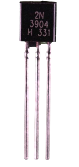
| Package Type | TO-92 | Standard through-hole package. |
Pin Configuration
The 2N3904 is housed in a TO-92 package with three pins. The pinout is as follows:
| Pin Number | Pin Name | Description |
|---|---|---|
| 1 | Emitter (E) | Current flows out of the transistor. |
| 2 | Base (B) | Controls the transistor's operation. |
| 3 | Collector (C) | Current flows into the transistor. |
Below is a diagram of the TO-92 package for reference:
   _______
  |       |
  |  2N   |
  | 3904  |
  |_______|
   | | |
   E B C
  (Front View)
3. Usage Instructions
Using the 2N3904 in a Circuit
The 2N3904 can be used in two primary modes: switching and amplification.
1. Switching Mode
In switching mode, the transistor acts as an electronic switch. When a small current is applied to the base, it allows a larger current to flow from the collector to the emitter.
Example Circuit: Controlling an LED with an Arduino UNO
- Connect the emitter to ground.
- Connect the collector to one terminal of the LED (with a current-limiting resistor in series).
- Connect the other terminal of the LED to the positive voltage supply.
- Use a resistor (typically 1kΩ) between the Arduino's digital pin and the base of the transistor.
Arduino Code Example:
// Define the pin connected to the transistor's base
const int transistorBasePin = 9;

void setup() {
  pinMode(transistorBasePin, OUTPUT); // Set the pin as an output
}

void loop() {
  digitalWrite(transistorBasePin, HIGH); // Turn on the transistor (LED ON)
  delay(1000);                           // Wait for 1 second
  digitalWrite(transistorBasePin, LOW);  // Turn off the transistor (LED OFF)
  delay(1000);                           // Wait for 1 second
}
2. Amplification Mode
In amplification mode, the transistor amplifies a small input signal at the base into a larger output signal at the collector. This is commonly used in audio or RF circuits.
Example Circuit: Audio Amplifier
- Connect the emitter to ground through a resistor.
- Connect the base to the input signal through a coupling capacitor and a biasing resistor.
- Connect the collector to the positive voltage supply through a load resistor.
Important Considerations
- Base Resistor: Always use a resistor between the base and the control signal to limit the base current and prevent damage to the transistor.
- Power Dissipation: Ensure the transistor does not exceed its maximum power dissipation (625mW). Use a heatsink if necessary.
- Voltage Ratings: Do not exceed the maximum voltage ratings (e.g., 40V for VCEO).
- Current Ratings: Ensure the collector current does not exceed 200mA.
4. Troubleshooting and FAQs
Common Issues and Solutions
| Issue | Possible Cause | Solution |
|---|---|---|
| Transistor does not turn on | Insufficient base current | Use a smaller base resistor to increase current. |
| Transistor overheats | Exceeding power dissipation limit | Reduce load current or use a heatsink. |
| Output signal is distorted | Incorrect biasing in amplification mode | Adjust biasing resistors for proper operation. |
| LED does not light up in switching mode | Incorrect wiring or damaged transistor | Double-check connections and replace the transistor if necessary. |
Frequently Asked Questions (FAQs)
Q1: Can I use the 2N3904 to drive a motor?
A1: The 2N3904 can drive small motors with currents below 200mA. For larger motors, use a power transistor or MOSFET.
Q2: What is the purpose of the base resistor?
A2: The base resistor limits the current flowing into the base to prevent damage to the transistor and the control circuit.
Q3: Can the 2N3904 be used in high-frequency circuits?
A3: Yes, the 2N3904 has a transition frequency (fT) of 300MHz, making it suitable for high-frequency applications.
Q4: How do I test if my 2N3904 is working?
A4: Use a multimeter in diode mode to check the base-emitter and base-collector junctions. Both should show a forward voltage drop (~0.6–0.7V) when forward-biased.
This documentation provides a comprehensive guide to understanding, using, and troubleshooting the 2N3904 NPN BJT transistor. Whether you're a beginner or an experienced engineer, the 2N3904 is a versatile and reliable component for your electronic projects.
Explore Projects Built with 2N3904 NPN BJT Transistor


Explore Projects Built with 2N3904 NPN BJT Transistor