Cirkit Designer
Your all-in-one circuit design IDE
Home /
Component Documentation
How to Use GPS: Examples, Pinouts, and Specs
Introduction
The H-RTK F9P Ultralight by Holybro is a high-precision Global Positioning System (GPS) module designed to provide accurate location and time information. This module leverages satellite-based navigation to deliver reliable data in all weather conditions, making it an essential component for various applications.
Explore Projects Built with GPS
ESP32-Based GPS Tracker with OLED Display and Telegram Integration

This circuit is a GPS-based tracking system that uses an ESP32 microcontroller to receive GPS data from a NEO 6M module and display the coordinates on a 1.3" OLED screen. It also features WiFi connectivity to send location updates to a remote server, potentially for applications such as asset tracking or navigation assistance.
ESP32-Based GPS Tracker with OLED Display and Firebase Integration

This circuit is a GPS tracking system that uses an ESP32 microcontroller to read location data from a NEO-6M GPS module and display information on a 0.96" OLED screen. The system is powered by a 2000mAh battery with a lithium-ion charger, and it uploads the GPS data to Firebase via WiFi. Additional components include an MPU6050 accelerometer/gyroscope for motion sensing and a buzzer for alerts.
Arduino Nano GPS Tracker with GSM and OLED Display

This circuit is a GPS tracking system that uses an Arduino Nano to interface with a SIM800L GSM module, a GPS NEO 6M module, and a 1.3-inch OLED display. The Arduino collects GPS data, displays it on the OLED screen, and sends the coordinates via SMS using the GSM module.
Arduino UNO-Based GPS and GSM-Enabled Vibration Sensor System with Motor Control
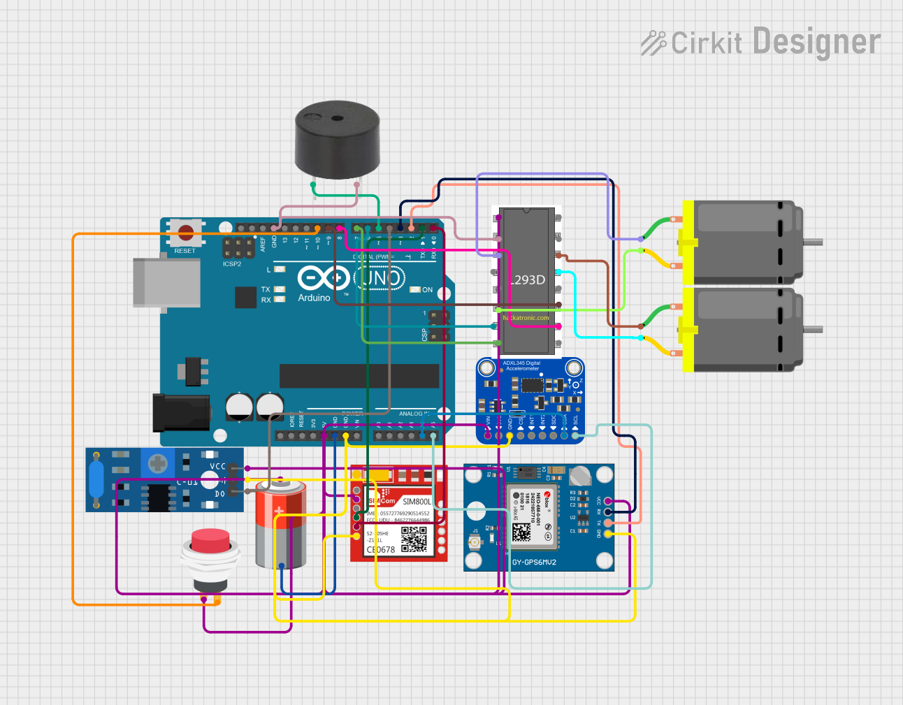
This circuit is a GPS-based tracking system with vibration detection and motor control capabilities. It uses an Arduino UNO to interface with a Neo 6M GPS module for location data, a Sim800l module for GSM communication, an ADXL345 accelerometer for motion sensing, and an SW-420 vibration sensor to detect vibrations. The system also includes a motor driver to control two DC motors and a buzzer for alerts, all powered by a 5V battery.
Explore Projects Built with GPS
ESP32-Based GPS Tracker with OLED Display and Telegram Integration
This circuit is a GPS-based tracking system that uses an ESP32 microcontroller to receive GPS data from a NEO 6M module and display the coordinates on a 1.3" OLED screen. It also features WiFi connectivity to send location updates to a remote server, potentially for applications such as asset tracking or navigation assistance.
ESP32-Based GPS Tracker with OLED Display and Firebase Integration
This circuit is a GPS tracking system that uses an ESP32 microcontroller to read location data from a NEO-6M GPS module and display information on a 0.96" OLED screen. The system is powered by a 2000mAh battery with a lithium-ion charger, and it uploads the GPS data to Firebase via WiFi. Additional components include an MPU6050 accelerometer/gyroscope for motion sensing and a buzzer for alerts.
Arduino Nano GPS Tracker with GSM and OLED Display
This circuit is a GPS tracking system that uses an Arduino Nano to interface with a SIM800L GSM module, a GPS NEO 6M module, and a 1.3-inch OLED display. The Arduino collects GPS data, displays it on the OLED screen, and sends the coordinates via SMS using the GSM module.
Arduino UNO-Based GPS and GSM-Enabled Vibration Sensor System with Motor Control
This circuit is a GPS-based tracking system with vibration detection and motor control capabilities. It uses an Arduino UNO to interface with a Neo 6M GPS module for location data, a Sim800l module for GSM communication, an ADXL345 accelerometer for motion sensing, and an SW-420 vibration sensor to detect vibrations. The system also includes a motor driver to control two DC motors and a buzzer for alerts, all powered by a 5V battery.
Common Applications and Use Cases
- Drones and UAVs: For precise navigation and positioning.
- Robotics: To enable autonomous movement and location tracking.
- Geocaching: For accurate location-based activities.
- Surveying: High-precision measurements for land and construction surveys.
- Automotive Navigation: Enhanced GPS accuracy for vehicle navigation systems.
Technical Specifications
Key Technical Details
| Specification | Value |
|---|---|
| Manufacturer | Holybro |
| Part ID | H-RTK F9P Ultralight |
| Voltage Range | 3.3V - 5V |
| Current Consumption | 120mA (typical) |
| Position Accuracy | Horizontal: 10mm, Vertical: 20mm |
| Update Rate | Up to 10 Hz |
| Communication | UART, I2C, SPI |
| Operating Temperature | -40°C to +85°C |
| Dimensions | 50mm x 50mm x 15mm |
| Weight | 20g |
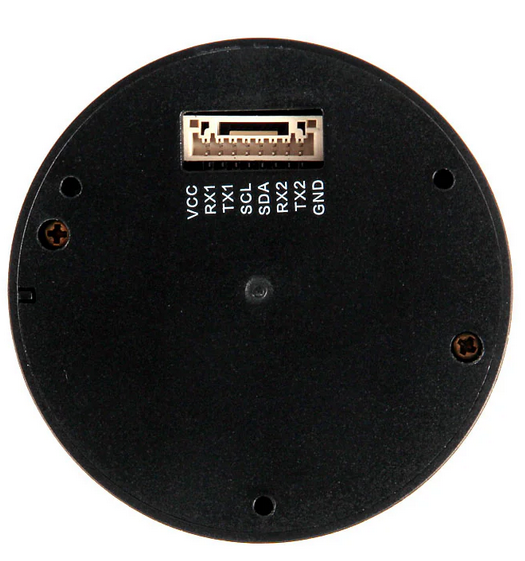
Pin Configuration and Descriptions
| Pin Number | Pin Name | Description |
|---|---|---|
| 1 | VCC | Power supply (3.3V - 5V) |
| 2 | GND | Ground |
| 3 | TX | UART Transmit |
| 4 | RX | UART Receive |
| 5 | SCL | I2C Clock |
| 6 | SDA | I2C Data |
| 7 | SPI_CS | SPI Chip Select |
| 8 | SPI_MOSI | SPI Master Out Slave In |
| 9 | SPI_MISO | SPI Master In Slave Out |
| 10 | SPI_SCK | SPI Clock |
Usage Instructions
How to Use the Component in a Circuit
- Power Supply: Connect the VCC pin to a 3.3V or 5V power source and the GND pin to the ground.
- Communication Interface: Choose the communication interface (UART, I2C, or SPI) based on your application.
- UART: Connect TX to the RX pin of your microcontroller and RX to the TX pin.
- I2C: Connect SCL to the I2C clock pin and SDA to the I2C data pin of your microcontroller.
- SPI: Connect SPI_CS, SPI_MOSI, SPI_MISO, and SPI_SCK to the corresponding SPI pins on your microcontroller.
- Antenna: Ensure the GPS module has a clear view of the sky for optimal satellite signal reception.
Important Considerations and Best Practices
- Antenna Placement: Place the GPS antenna in an open area with minimal obstructions to ensure the best signal reception.
- Power Supply: Use a stable power supply to avoid fluctuations that could affect the GPS module's performance.
- Baud Rate: Configure the UART baud rate to match the GPS module's default setting (typically 9600 or 115200 bps).
- Data Parsing: Use appropriate libraries or code to parse the NMEA sentences received from the GPS module.
Example Code for Arduino UNO
#include <SoftwareSerial.h>
#include <TinyGPS++.h>

// Create a SoftwareSerial object for GPS communication
SoftwareSerial ss(4, 3); // RX, TX

// Create a TinyGPS++ object
TinyGPSPlus gps;

void setup() {
  Serial.begin(9600); // Initialize serial communication with the PC
  ss.begin(9600);     // Initialize serial communication with the GPS module
  Serial.println("GPS Module Test");
}

void loop() {
  while (ss.available() > 0) {
    gps.encode(ss.read()); // Decode the data from the GPS module

    if (gps.location.isUpdated()) {
      // Print the latitude and longitude
      Serial.print("Latitude: ");
      Serial.println(gps.location.lat(), 6);
      Serial.print("Longitude: ");
      Serial.println(gps.location.lng(), 6);
    }
  }
}
Troubleshooting and FAQs
Common Issues Users Might Face
No GPS Fix:
- Solution: Ensure the GPS antenna has a clear view of the sky and wait for a few minutes for the module to acquire satellite signals.
Incorrect Data:
- Solution: Verify the baud rate settings and ensure the communication interface is correctly configured.
Intermittent Signal:
- Solution: Check for any obstructions or sources of interference near the GPS antenna.
Solutions and Tips for Troubleshooting
- Check Connections: Ensure all connections are secure and correctly wired.
- Update Firmware: Check for any available firmware updates for the GPS module and apply them if necessary.
- Use External Antenna: If the built-in antenna is not providing a strong signal, consider using an external GPS antenna.
By following this documentation, users can effectively integrate and utilize the H-RTK F9P Ultralight GPS module in their projects, ensuring accurate and reliable location data.