How to Use ac dimmer: Examples, Pinouts, and Specs
AC Dimmer Documentation
1. Introduction
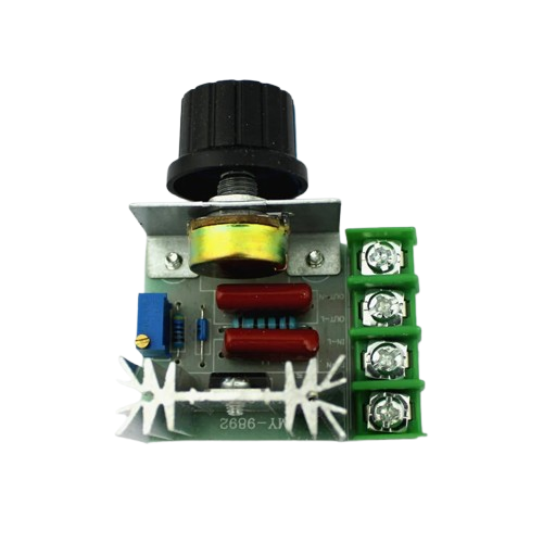
An AC dimmer is an electronic component designed to control the brightness of incandescent bulbs, dimmable LED lights, and other AC-powered devices by adjusting the voltage and current supplied to the load. It operates by modifying the phase angle of the AC waveform, effectively controlling the power delivered to the connected device.
AC dimmers are widely used in home automation, lighting control systems, and industrial applications where precise control of AC loads is required. They are compatible with microcontrollers like the Arduino, making them a popular choice for DIY projects and smart home setups.
Common Applications:
- Dimming incandescent and dimmable LED lights
- Speed control of AC motors (e.g., fans)
- Home automation systems
- Theater and stage lighting
- Industrial AC load control
2. Technical Specifications
Below are the key technical details and pin configuration of a typical AC dimmer module:
Key Technical Details
| Parameter | Value |
|---|---|
| Input Voltage | 110V AC or 220V AC (region-specific) |
| Output Voltage | Adjustable (0% to ~100% of input voltage) |
| Maximum Load Power | 400W to 2000W (varies by model) |
| Control Voltage | 3.3V to 5V (logic level) |
| Trigger Type | Zero-crossing detection |
| Isolation | Optocoupler-based isolation |
| Operating Temperature | -20°C to 85°C |
Pin Configuration and Descriptions
| Pin Name | Type | Description |
|---|---|---|
| AC-IN | Input | Connects to the live and neutral wires of the AC mains supply. |
| AC-OUT | Output | Connects to the load (e.g., light bulb, fan). |
| GND | Ground | Ground connection for the control circuit. |
| VCC | Power Input | 3.3V or 5V input to power the control circuit. |
| PWM/Signal | Control Signal | Accepts a PWM signal from a microcontroller (e.g., Arduino) to control dimming. |
3. Usage Instructions
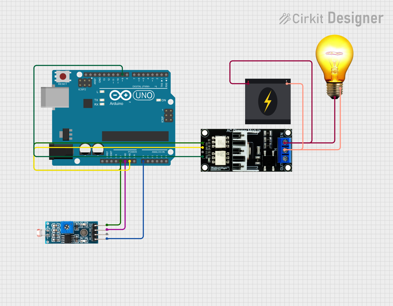
How to Use the AC Dimmer in a Circuit
Connect the AC Mains:
- Connect the live and neutral wires of the AC mains supply to the
AC-INterminals of the dimmer module. - Ensure proper insulation and safety precautions when working with high-voltage AC.
- Connect the live and neutral wires of the AC mains supply to the
Connect the Load:
- Attach the load (e.g., a light bulb or fan) to the
AC-OUTterminals of the dimmer module.
- Attach the load (e.g., a light bulb or fan) to the
Connect the Control Circuit:
- Connect the
GNDpin of the dimmer module to the ground of your microcontroller (e.g., Arduino). - Connect the
VCCpin to the 3.3V or 5V power supply of the microcontroller. - Connect the
PWM/Signalpin to a PWM-capable pin on the microcontroller.
- Connect the
Upload the Code:
- Use the provided Arduino code (see below) to send a PWM signal to the dimmer module, controlling the brightness of the connected load.
Important Considerations and Best Practices
- Safety First: Always ensure proper insulation and avoid touching live AC connections. Use a fuse for added protection.
- Load Compatibility: Ensure the connected load is compatible with dimming (e.g., dimmable LEDs or incandescent bulbs).
- Zero-Crossing Detection: The dimmer module relies on zero-crossing detection for smooth operation. Ensure the control signal is synchronized with the AC mains.
- Avoid Overloading: Do not exceed the maximum load power rating of the dimmer module.
4. Example Arduino Code
Below is an example Arduino sketch to control an AC dimmer using a PWM signal:
/*
  AC Dimmer Control Example
  This code demonstrates how to control an AC dimmer module using an Arduino.
  The brightness of the connected load is adjusted using a potentiometer.

  Connections:
  - PWM/Signal pin of the dimmer module to Arduino pin 9
  - GND of the dimmer module to Arduino GND
  - VCC of the dimmer module to Arduino 5V
*/

#define DIMMER_PIN 9  // PWM pin connected to the dimmer module
#define POT_PIN A0    // Analog pin connected to the potentiometer

void setup() {
  pinMode(DIMMER_PIN, OUTPUT);  // Set the dimmer pin as an output
}

void loop() {
  int potValue = analogRead(POT_PIN);  // Read the potentiometer value (0-1023)
  int pwmValue = map(potValue, 0, 1023, 0, 255);  // Map to PWM range (0-255)

  analogWrite(DIMMER_PIN, pwmValue);  // Send PWM signal to the dimmer module

  delay(10);  // Small delay for stability
}
5. Troubleshooting and FAQs
Common Issues and Solutions
| Issue | Possible Cause | Solution |
|---|---|---|
| Load does not dim or flickers | Incorrect wiring or incompatible load | Verify wiring and ensure the load is dimmable (e.g., dimmable LED or incandescent). |
| Dimmer module overheats | Load exceeds maximum power rating | Reduce the load or use a higher-rated dimmer module. |
| No response to PWM signal | Incorrect control signal or wiring | Check the PWM pin connection and ensure the microcontroller is functioning. |
| Brightness control is not smooth | PWM signal not synchronized with AC mains | Use a library or code that accounts for zero-crossing detection. |
FAQs
Can I use the AC dimmer with non-dimmable LEDs?
- No, non-dimmable LEDs are not compatible with AC dimmers and may get damaged.
Is the dimmer module safe to use with high-power loads?
- Yes, as long as the load does not exceed the maximum power rating of the module.
Can I control the dimmer with a 3.3V microcontroller like ESP32?
- Yes, most dimmer modules are compatible with 3.3V and 5V logic levels.
Do I need an external library for Arduino?
- For basic PWM control, no library is required. However, for advanced zero-crossing synchronization, libraries like RBDDimmer can be used.
6. Conclusion
The AC dimmer is a versatile and essential component for controlling AC loads in various applications. By following the guidelines and best practices outlined in this documentation, you can safely and effectively integrate the dimmer module into your projects. Whether you're building a smart lighting system or experimenting with home automation, the AC dimmer offers precise and reliable control over AC-powered devices.
Explore Projects Built with ac dimmer
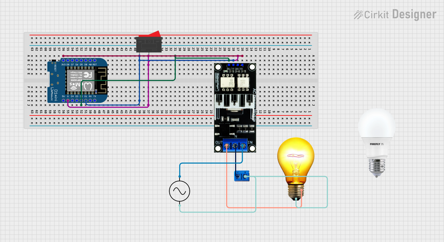
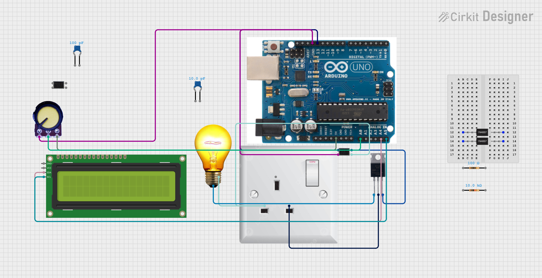
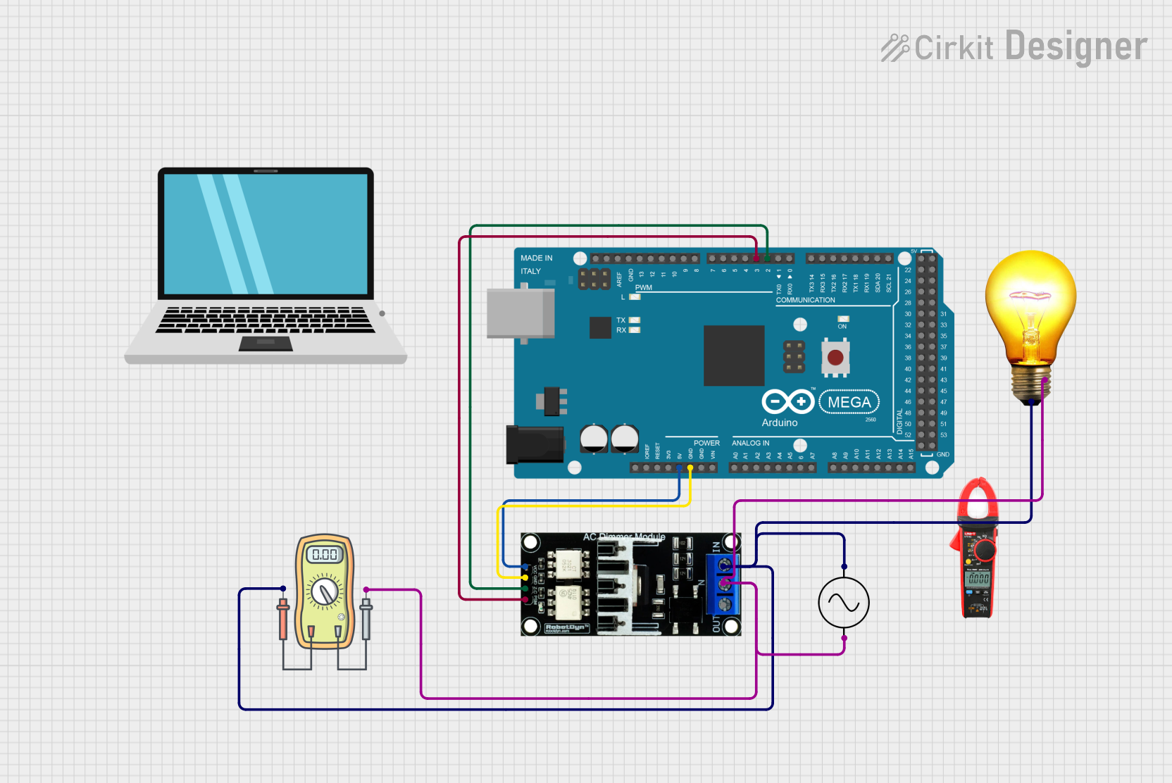
Explore Projects Built with ac dimmer