The 2437605-1, manufactured by TE Connectivity, is a HEADER ASSEMBLY, 23 POSITION, RIGHT ANGLE, AMPSEAL connector. This component is designed to provide reliable and robust electrical connections in various electronic and industrial applications. Its 23-position configuration and right-angle design make it suitable for compact and space-constrained setups.
Explore Projects Built with 2437605-1
Use Cirkit Designer to design, explore, and prototype these projects online. Some projects support real-time simulation. Click "Open Project" to start designing instantly!
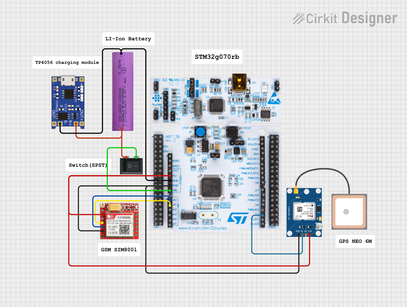
This circuit is an emergency alert system that uses a NUCLEO-F072RB microcontroller to send SMS alerts and make calls via a SIM800L GSM module, while obtaining location data from a GPS NEO 6M module. The system is powered by a Li-ion battery and includes a TP4056 module for battery charging and protection, with a rocker switch to control power to the microcontroller.
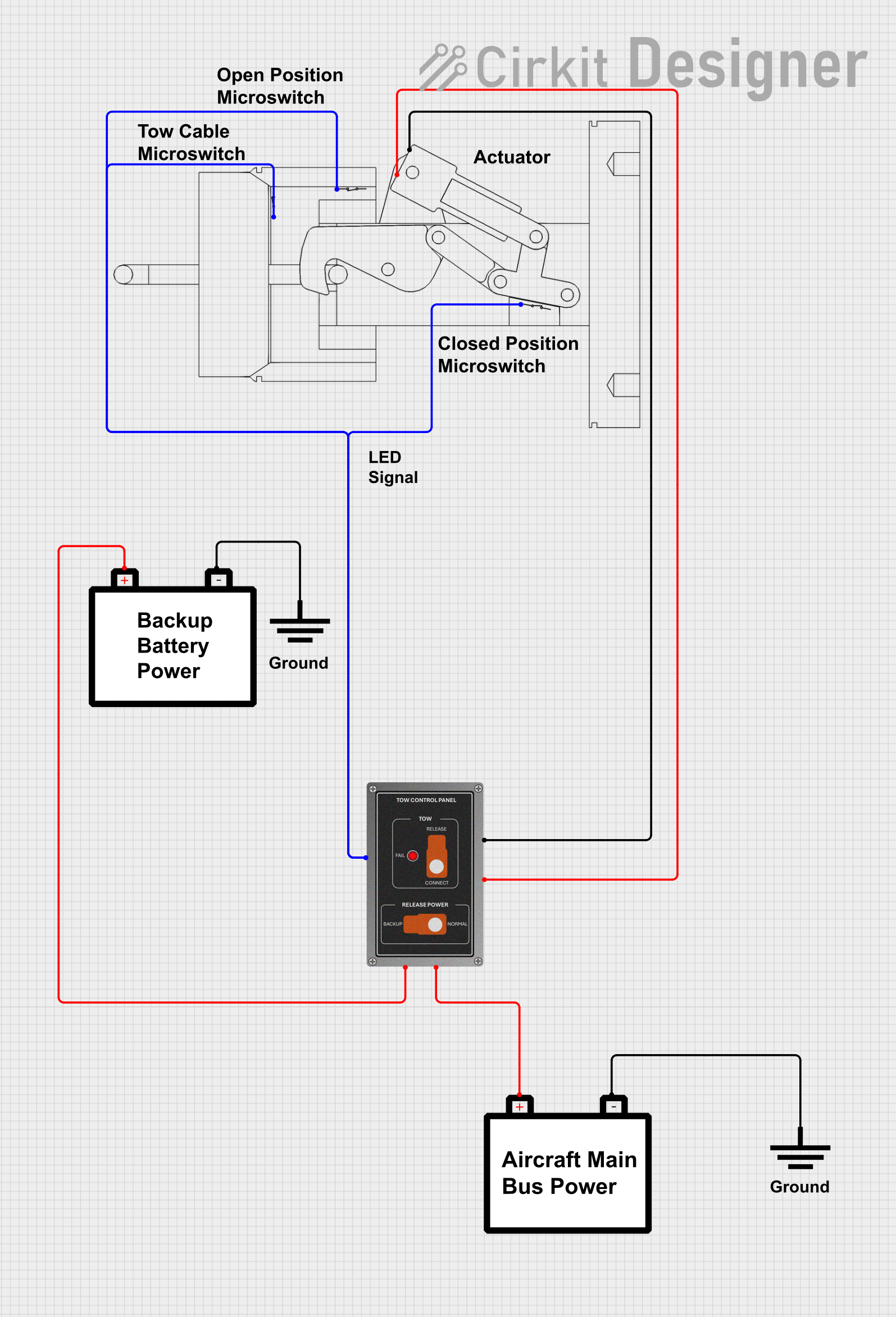
This circuit is designed for a tow release control system in an aircraft, featuring a P68 Tow Control Panel and a Tow Release With Switches assembly. The control panel receives power from two separate aircraft batteries, with one providing main power and the other serving as a backup. The Tow Release With Switches assembly is connected to the control panel, allowing for the actuation of the tow mechanism and providing feedback via an LED indicator.
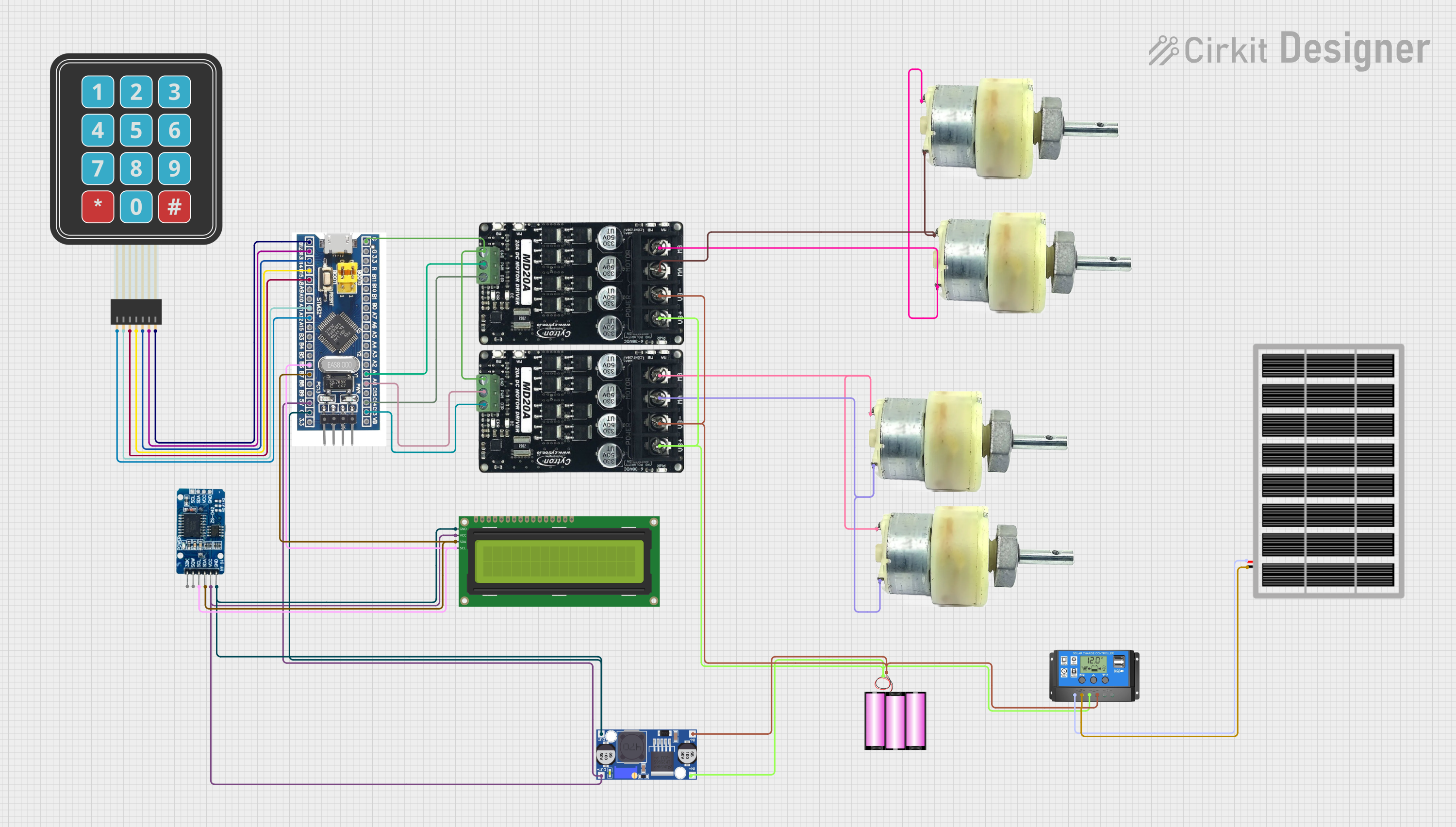
This circuit features an STM32F103C8T6 microcontroller interfaced with a membrane matrix keypad for input, an RTC DS3231 for real-time clock functionality, and a 16x2 I2C LCD for display. It controls four 12V geared motors through two MD20 CYTRON motor drivers, with the motor power supplied by a 12V battery regulated by a buck converter. The battery is charged via a solar panel connected through a solar charge controller, ensuring a renewable energy source for the system.
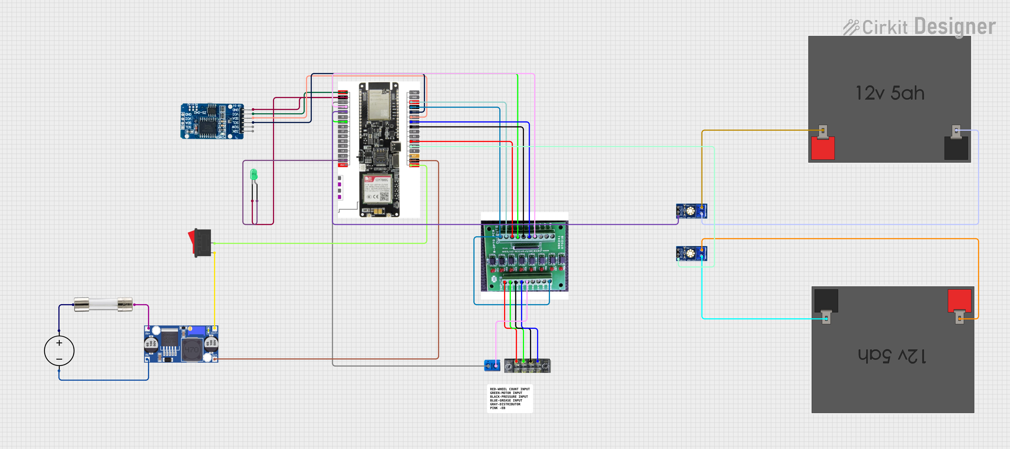
This circuit features a LilyGo-SIM7000G module for cellular communication and GPS functionality, interfaced with an RTC DS3231 for real-time clock capabilities. It includes voltage sensing through two voltage sensor modules, and uses an 8-channel opto-coupler for isolating different parts of the circuit. Power management is handled by a buck converter connected to a DC power source and batteries, with a fuse for protection and a rocker switch for on/off control. Additionally, there's an LED for indication purposes.
Applications requiring sealed and durable connectors
Technical Specifications
Key Technical Details
Parameter
Value
Manufacturer
TE Connectivity
Part Number
2437605-1
Connector Type
Header Assembly
Number of Positions
23
Mounting Type
Right Angle
Sealing
AMPSEAL (sealed for environmental protection)
Operating Temperature
-40°C to +125°C
Voltage Rating
250V (typical)
Current Rating
17A (maximum per contact)
Contact Material
Copper Alloy
Contact Plating
Tin
Housing Material
Thermoplastic
Pin Configuration and Descriptions
The 2437605-1 connector has 23 pins arranged in a single row. Below is the pin configuration:
Pin Number
Description
Notes
1-23
Signal or Power Connections
Configurable based on design
Note: The specific pin assignments depend on the application and wiring requirements. Refer to the system design documentation for detailed pin mapping.
Usage Instructions
How to Use the Component in a Circuit
Mounting the Connector:
The 2437605-1 is designed for PCB mounting in a right-angle orientation.
Ensure the PCB layout matches the connector's footprint for proper alignment.
Wiring and Connections:
Use compatible AMPSEAL connectors or mating parts for secure connections.
Crimp the wires to the mating connector terminals using the recommended crimping tool.
Environmental Sealing:
Ensure the connector is properly sealed to maintain its environmental protection rating.
Verify that the mating connector is fully engaged to prevent moisture ingress.
Voltage and Current Ratings:
Do not exceed the specified voltage (250V) and current (17A per contact) ratings.
Use appropriate wire gauges to handle the current requirements.
Important Considerations and Best Practices
Temperature Range: Operate the connector within the specified temperature range (-40°C to +125°C).
Mating Cycles: The connector is rated for a limited number of mating cycles. Avoid excessive disconnections to maintain reliability.
Inspection: Periodically inspect the connector for signs of wear, corrosion, or damage.
Soldering: If soldering is required, follow the recommended soldering guidelines to avoid damaging the thermoplastic housing.
Example: Connecting to an Arduino UNO
While the 2437605-1 is not directly designed for Arduino projects, it can be used in custom setups where robust connections are required. Below is an example of how to interface the connector with an Arduino UNO for a simple signal transmission:
// Example: Reading a signal from a device connected via the 2437605-1 connector
// Pin 1 of the connector is used for signal input, connected to Arduino pin A0

const int signalPin = A0; // Define the Arduino analog pin connected to the signal
int signalValue = 0;      // Variable to store the signal value

void setup() {
  Serial.begin(9600); // Initialize serial communication for debugging
  pinMode(signalPin, INPUT); // Set the signal pin as input
}

void loop() {
  signalValue = analogRead(signalPin); // Read the signal value
  Serial.print("Signal Value: ");      // Print the signal value to the serial monitor
  Serial.println(signalValue);
  delay(500); // Wait for 500ms before the next reading
}
Note: Ensure proper wiring and grounding when interfacing the connector with an Arduino or other microcontroller.
Troubleshooting and FAQs
Common Issues and Solutions
Issue
Possible Cause
Solution
Loose connection
Improper mating of connectors
Ensure connectors are fully engaged.
Signal loss or noise
Poor crimping or damaged wires
Re-crimp or replace damaged wires.
Overheating
Exceeding current rating
Use appropriate wire gauge and reduce load.
Moisture ingress
Improper sealing of the connector
Verify sealing and replace damaged seals.
FAQs
Can the 2437605-1 be used in outdoor applications?
Yes, the AMPSEAL design provides environmental sealing, making it suitable for outdoor use.
What tools are recommended for crimping?
Use TE Connectivity's recommended crimping tools for optimal results.
How do I ensure proper alignment during PCB mounting?
Use alignment pins or guides on the PCB to match the connector's footprint.
What is the maximum wire size supported?
The connector supports wire sizes up to 16 AWG, depending on the application.
By following the guidelines and best practices outlined in this documentation, you can ensure reliable and efficient use of the 2437605-1 connector in your projects.


 Open Project in Cirkit Designer