How to Use horn: Examples, Pinouts, and Specs
Introduction
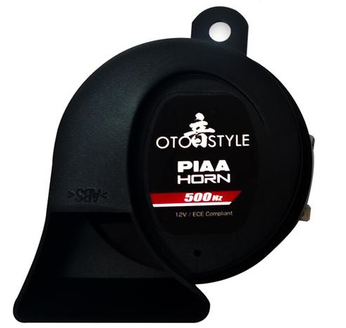
A horn is an acoustic device that produces sound by converting electrical energy into sound energy. It typically uses a vibrating diaphragm to generate sound waves. Horns are widely used in vehicles as signaling devices, in alarm systems, and in industrial applications where audible alerts are required. Their ability to produce loud and attention-grabbing sounds makes them essential in safety and communication systems.
Explore Projects Built with horn
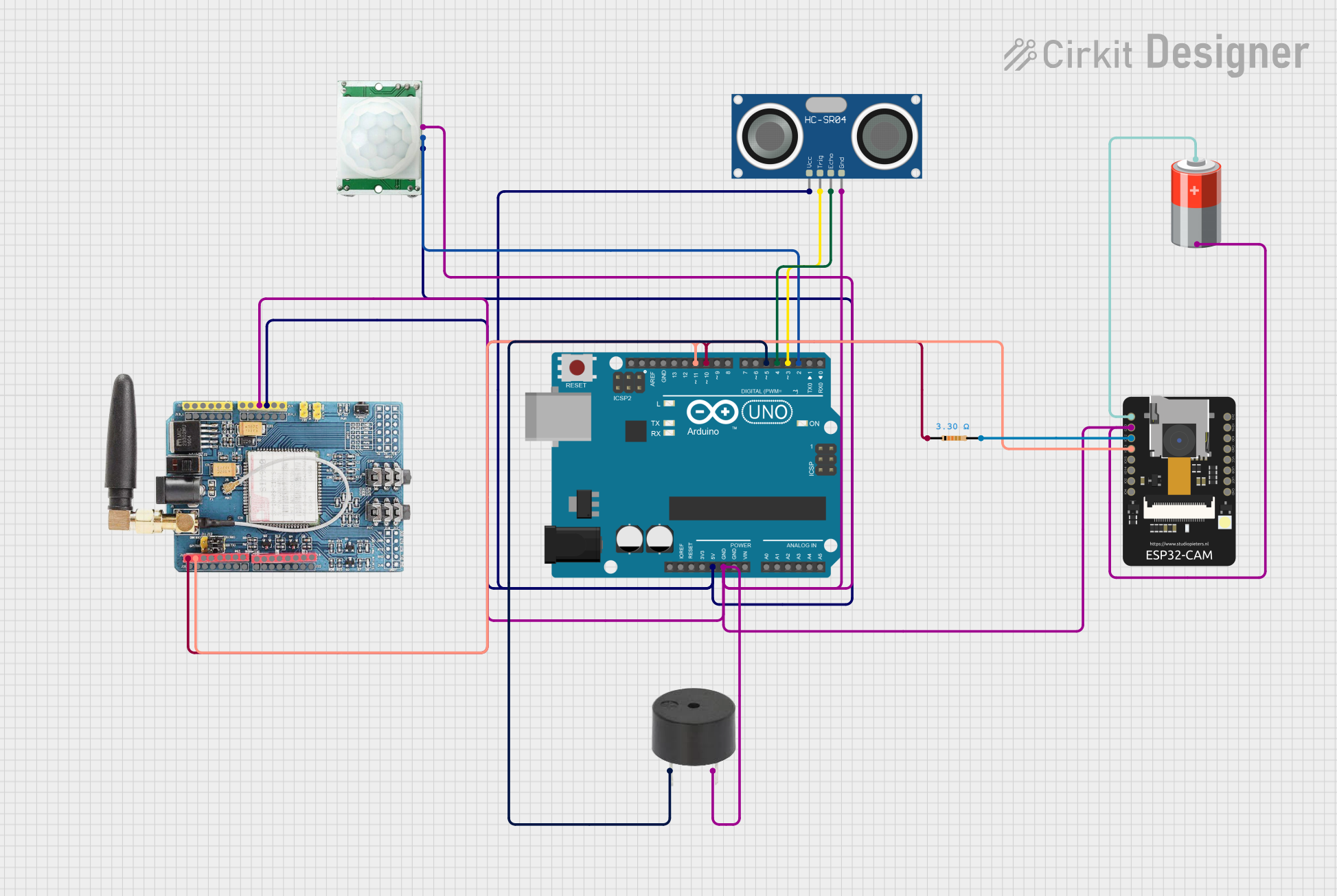
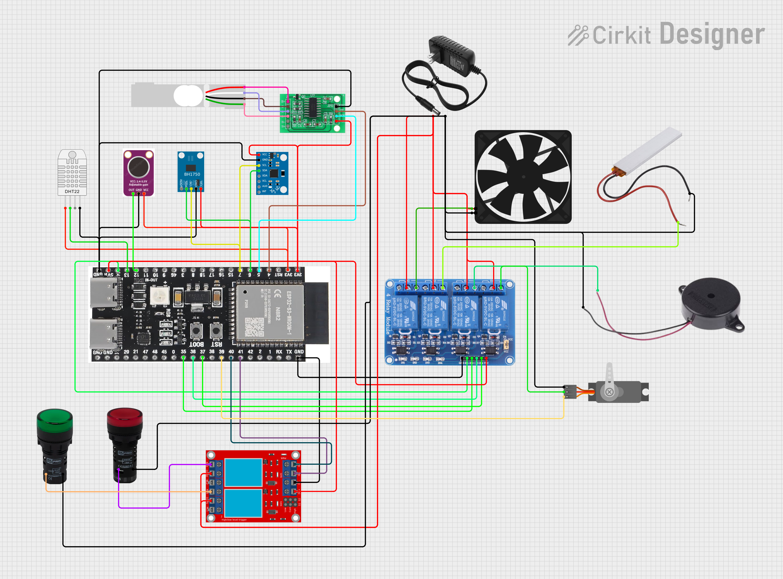
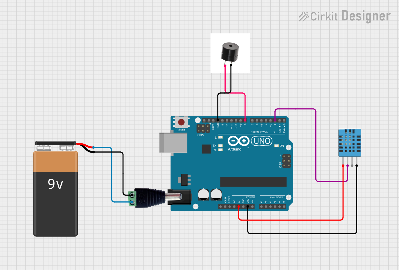
Explore Projects Built with horn
Common Applications
- Vehicle signaling (e.g., car horns, bike horns)
- Alarm systems (e.g., fire alarms, security alarms)
- Industrial machinery alerts
- Public address systems
- Emergency signaling devices
Technical Specifications
Below are the general technical specifications for a typical electronic horn. Note that specific models may vary, so always refer to the datasheet of your particular horn.
| Parameter | Value |
|---|---|
| Operating Voltage | 6V to 24V DC |
| Current Consumption | 0.5A to 3A (depending on model) |
| Sound Pressure Level | 90dB to 120dB at 1 meter |
| Frequency Range | 300Hz to 4kHz |
| Operating Temperature | -20°C to 70°C |
| Housing Material | Plastic or metal |
Pin Configuration
Horns typically have two terminals for electrical connections:
| Pin | Description |
|---|---|
| Positive (+) | Connect to the positive terminal of the power supply or control circuit. |
| Negative (-) | Connect to the ground or negative terminal of the power supply. |
Usage Instructions
How to Use the Horn in a Circuit
- Power Supply: Ensure the horn is powered within its specified voltage range (e.g., 12V DC for most vehicle horns). Exceeding the voltage rating may damage the horn.
- Connection:
- Connect the positive terminal of the horn to the power supply or a control circuit (e.g., a relay or microcontroller output).
- Connect the negative terminal to the ground.
- Control Circuit: If the horn is to be controlled by a microcontroller (e.g., Arduino UNO), use a relay or transistor to handle the high current required by the horn. Microcontroller pins cannot directly drive the horn due to current limitations.
Example Circuit with Arduino UNO
Below is an example of how to control a horn using an Arduino UNO and a relay module.
Components Required:
- Horn
- Arduino UNO
- Relay module
- 12V power supply
- Connecting wires
Circuit Diagram:
- Connect the relay module's input pin to an Arduino digital pin (e.g., pin 7).
- Connect the relay's output terminals to the horn and the 12V power supply.
- Ensure the ground of the Arduino and the power supply are connected.
Arduino Code:
// Example code to control a horn using Arduino UNO and a relay module

const int relayPin = 7; // Pin connected to the relay module

void setup() {
  pinMode(relayPin, OUTPUT); // Set relay pin as output
  digitalWrite(relayPin, LOW); // Ensure the relay is off initially
}

void loop() {
  digitalWrite(relayPin, HIGH); // Turn on the horn
  delay(1000); // Horn sounds for 1 second
  digitalWrite(relayPin, LOW); // Turn off the horn
  delay(2000); // Wait for 2 seconds before sounding again
}
Important Considerations
- Current Handling: Ensure the relay or transistor used can handle the horn's current requirements.
- Polarity: Always connect the horn with the correct polarity to avoid damage.
- Safety: Avoid prolonged activation of the horn, as it may overheat or cause unnecessary noise pollution.
Troubleshooting and FAQs
Common Issues and Solutions
| Issue | Possible Cause | Solution |
|---|---|---|
| Horn does not sound | No power supply or loose connections | Check power supply and wiring. |
| Horn sounds weak or distorted | Insufficient voltage or current | Ensure the power supply meets the horn's requirements. |
| Horn overheats | Prolonged activation or overvoltage | Limit activation time and check voltage. |
| Relay does not activate the horn | Incorrect wiring or insufficient current | Verify relay wiring and ensure it can handle the horn's current. |
FAQs
Can I connect the horn directly to an Arduino pin?
- No, Arduino pins cannot supply the high current required by the horn. Use a relay or transistor for control.
What type of relay should I use?
- Use a relay rated for at least the horn's operating voltage and current (e.g., 12V, 10A).
Can I use the horn with an AC power supply?
- No, most electronic horns are designed for DC operation. Check the specifications of your horn.
Why is my horn making a clicking sound instead of a continuous tone?
- This may indicate insufficient power or a faulty horn. Check the power supply and connections.
By following this documentation, you can effectively integrate and troubleshoot a horn in your electronic projects. Always refer to the specific datasheet for your horn model for precise details.