Cirkit Designer Logo
Cirkit Designer
Your all-in-one circuit design IDE
Home / 
Component Documentation

How to Use MBR20100CT: Examples, Pinouts, and Specs
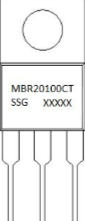

Image of MBR20100CT
Cirkit Designer LogoDesign with MBR20100CT in Cirkit Designer

Introduction

The MBR20100CT is a Schottky barrier rectifier diode designed for high-efficiency rectification in power supply circuits and other electronic applications. With a maximum reverse voltage of 100V and a forward current rating of 20A, it is ideal for applications requiring low forward voltage drop and high current handling. Its dual-diode configuration in a TO-220 package makes it suitable for compact designs and high-power applications.

Explore Projects Built with MBR20100CT

Use Cirkit Designer to design, explore, and prototype these projects online. Some projects support real-time simulation. Click "Open Project" to start designing instantly!
Satellite-Based Timing and Navigation System with SDR and Atomic Clock Synchronization
Image of GPS 시스템 측정 구성도_Confirm: A project utilizing MBR20100CT in a practical application
This circuit appears to be a complex system involving power supply management, GPS and timing synchronization, and data communication. It includes a SI-TEX G1 Satellite Compass for GPS data, an XHTF1021 Atomic Rubidium Clock for precise timing, and Ettus USRP B200 units for software-defined radio communication. Power is supplied through various SMPS units and distributed via terminal blocks and DC jacks. Data communication is facilitated by Beelink MINI S12 N95 computers, RS232 splitters, and a 1000BASE-T Media Converter for network connectivity. RF Directional Couplers are used to interface antennas with the USRP units, and the entire system is likely contained within cases for protection and organization.
Cirkit Designer LogoOpen Project in Cirkit Designer
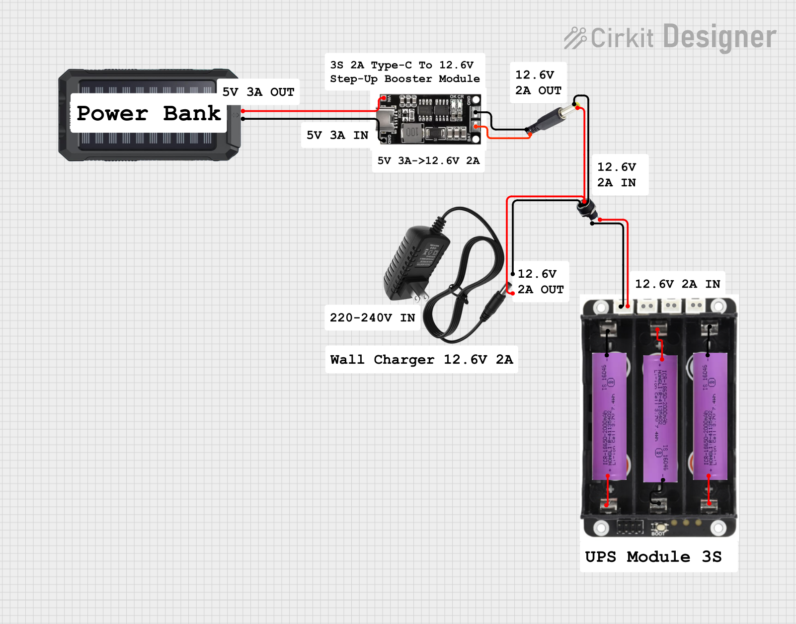
Battery-Powered UPS System with Waveshare UPS 3S and Solar Charger
Image of Copy of s: A project utilizing MBR20100CT in a practical application
This circuit is a power management system that integrates a 12V power supply, a solar charger power bank, and multiple Li-ion batteries to provide a stable power output. The Waveshare UPS 3S manages the input from the power sources and batteries, ensuring continuous power delivery. The MRB045 module is used to interface the solar charger with the rest of the system.
Cirkit Designer LogoOpen Project in Cirkit Designer
Satellite Compass and Network-Integrated GPS Data Processing System
Image of GPS 시스템 측정 구성도_241016: A project utilizing MBR20100CT in a practical application
This circuit comprises a satellite compass, a mini PC, two GPS antennas, power supplies, a network switch, media converters, and an atomic rubidium clock. The satellite compass is powered by a triple output DC power supply and interfaces with an RS232 splitter for 1PPS signals. The mini PCs are connected to the USRP B200 devices via USB for data and power, and to media converters via Ethernet, which in turn connect to a network switch using fiber optic links. The antennas are connected to the USRP B200s through RF directional couplers, and the atomic clock provides a 1PPS input to the RS232 splitter.
Cirkit Designer LogoOpen Project in Cirkit Designer
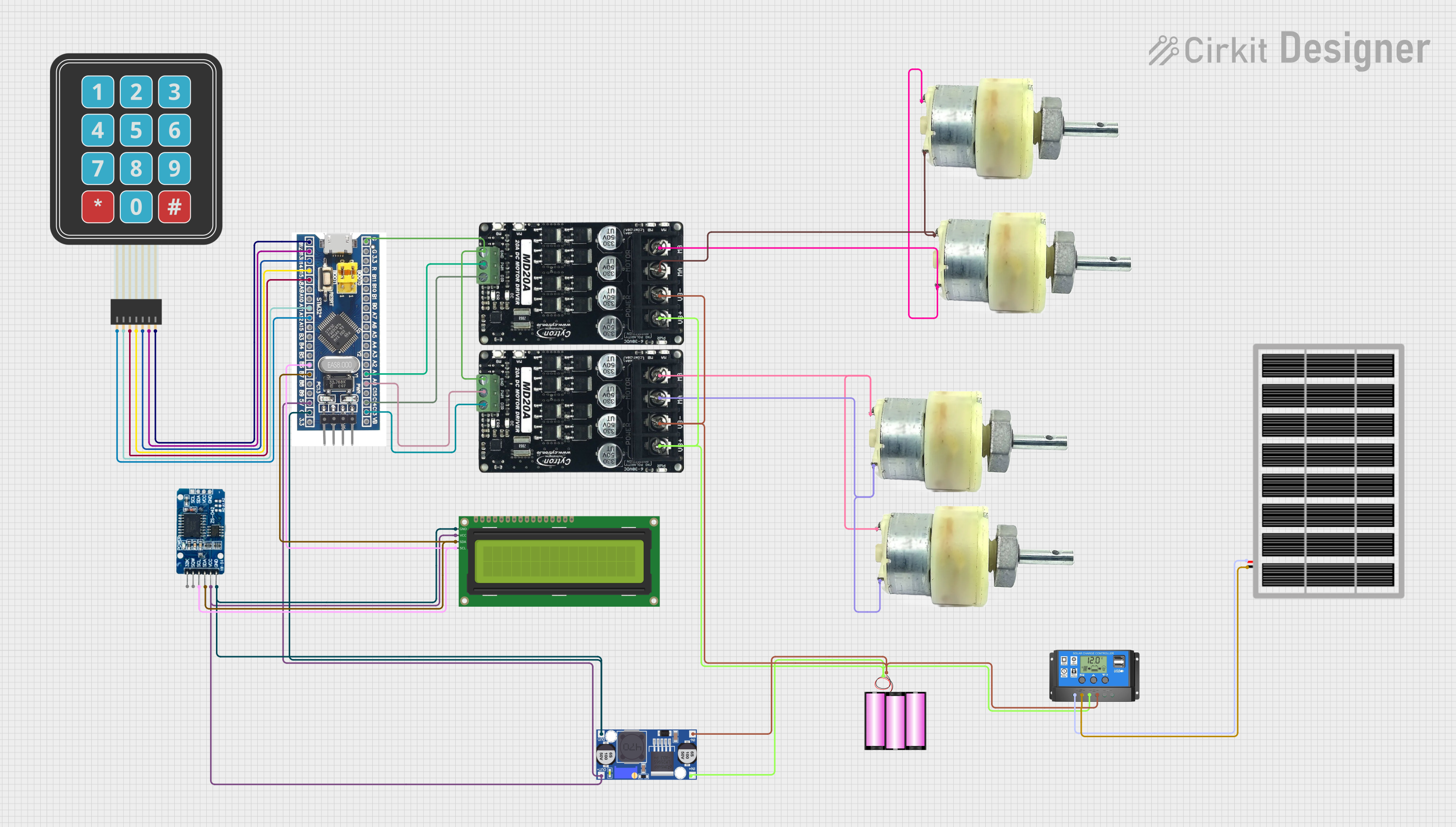
Solar-Powered STM32-Based Automation System with Matrix Keypad and RTC
Image of soloar cleaner : A project utilizing MBR20100CT in a practical application
This circuit features an STM32F103C8T6 microcontroller interfaced with a membrane matrix keypad for input, an RTC DS3231 for real-time clock functionality, and a 16x2 I2C LCD for display. It controls four 12V geared motors through two MD20 CYTRON motor drivers, with the motor power supplied by a 12V battery regulated by a buck converter. The battery is charged via a solar panel connected through a solar charge controller, ensuring a renewable energy source for the system.
Cirkit Designer LogoOpen Project in Cirkit Designer

Explore Projects Built with MBR20100CT

Use Cirkit Designer to design, explore, and prototype these projects online. Some projects support real-time simulation. Click "Open Project" to start designing instantly!
Image of GPS 시스템 측정 구성도_Confirm: A project utilizing MBR20100CT in a practical application
Satellite-Based Timing and Navigation System with SDR and Atomic Clock Synchronization
This circuit appears to be a complex system involving power supply management, GPS and timing synchronization, and data communication. It includes a SI-TEX G1 Satellite Compass for GPS data, an XHTF1021 Atomic Rubidium Clock for precise timing, and Ettus USRP B200 units for software-defined radio communication. Power is supplied through various SMPS units and distributed via terminal blocks and DC jacks. Data communication is facilitated by Beelink MINI S12 N95 computers, RS232 splitters, and a 1000BASE-T Media Converter for network connectivity. RF Directional Couplers are used to interface antennas with the USRP units, and the entire system is likely contained within cases for protection and organization.
Cirkit Designer LogoOpen Project in Cirkit Designer
Image of Copy of s: A project utilizing MBR20100CT in a practical application
Battery-Powered UPS System with Waveshare UPS 3S and Solar Charger
This circuit is a power management system that integrates a 12V power supply, a solar charger power bank, and multiple Li-ion batteries to provide a stable power output. The Waveshare UPS 3S manages the input from the power sources and batteries, ensuring continuous power delivery. The MRB045 module is used to interface the solar charger with the rest of the system.
Cirkit Designer LogoOpen Project in Cirkit Designer
Image of GPS 시스템 측정 구성도_241016: A project utilizing MBR20100CT in a practical application
Satellite Compass and Network-Integrated GPS Data Processing System
This circuit comprises a satellite compass, a mini PC, two GPS antennas, power supplies, a network switch, media converters, and an atomic rubidium clock. The satellite compass is powered by a triple output DC power supply and interfaces with an RS232 splitter for 1PPS signals. The mini PCs are connected to the USRP B200 devices via USB for data and power, and to media converters via Ethernet, which in turn connect to a network switch using fiber optic links. The antennas are connected to the USRP B200s through RF directional couplers, and the atomic clock provides a 1PPS input to the RS232 splitter.
Cirkit Designer LogoOpen Project in Cirkit Designer
Image of soloar cleaner : A project utilizing MBR20100CT in a practical application
Solar-Powered STM32-Based Automation System with Matrix Keypad and RTC
This circuit features an STM32F103C8T6 microcontroller interfaced with a membrane matrix keypad for input, an RTC DS3231 for real-time clock functionality, and a 16x2 I2C LCD for display. It controls four 12V geared motors through two MD20 CYTRON motor drivers, with the motor power supplied by a 12V battery regulated by a buck converter. The battery is charged via a solar panel connected through a solar charge controller, ensuring a renewable energy source for the system.
Cirkit Designer LogoOpen Project in Cirkit Designer

Common Applications

  • Power supply rectification
  • DC-DC converters
  • Battery chargers
  • Freewheeling diodes in motor control circuits
  • Polarity protection in electronic devices

Technical Specifications

Key Specifications

Parameter Value
Maximum Reverse Voltage 100V
Maximum Forward Current 20A
Forward Voltage Drop (Vf) 0.85V (typical at 10A)
Reverse Leakage Current 1mA (at 100V)
Operating Temperature Range -65°C to +150°C
Package Type TO-220

Pin Configuration

The MBR20100CT is a dual-diode rectifier in a TO-220 package. The pinout is as follows:

Pin Number Pin Name Description
1 Anode 1 Positive terminal of the first diode
2 Cathode (Common) Shared negative terminal for both diodes
3 Anode 2 Positive terminal of the second diode

Internal Schematic

The MBR20100CT contains two Schottky diodes connected in a common-cathode configuration.

Usage Instructions

How to Use the MBR20100CT in a Circuit

  1. Identify the Pins: Ensure proper identification of the anode and cathode pins using the pin configuration table above.
  2. Connect the Diode:
    • For rectification, connect the anodes (Pin 1 and Pin 3) to the AC input and the cathode (Pin 2) to the DC output.
    • For freewheeling or polarity protection, connect the cathode to the positive voltage rail and the anode to the load or ground.
  3. Heat Dissipation: The MBR20100CT can handle high currents, so ensure proper heat dissipation using a heatsink attached to the TO-220 package.
  4. Voltage and Current Ratings: Do not exceed the maximum reverse voltage (100V) or forward current (20A) to avoid damage.

Important Considerations

  • Heatsink Requirement: The TO-220 package requires a heatsink for high-current applications to prevent overheating.
  • Reverse Voltage: Ensure the reverse voltage in the circuit does not exceed 100V.
  • Parasitic Oscillations: Use decoupling capacitors in high-frequency circuits to minimize noise and oscillations.

Example: Using MBR20100CT with an Arduino UNO

The MBR20100CT can be used in a simple DC motor control circuit with an Arduino UNO to protect against back-EMF. Below is an example circuit and code:

Circuit Description

  • Connect the MBR20100CT across the motor terminals (cathode to the positive terminal, anode to the negative terminal).
  • This configuration protects the Arduino and motor driver from voltage spikes caused by the motor's inductive load.

Arduino Code

// Example code for controlling a DC motor with Arduino UNO
// and protecting the circuit using the MBR20100CT diode.

const int motorPin = 9; // PWM pin connected to motor driver input

void setup() {
  pinMode(motorPin, OUTPUT); // Set motor pin as output
}

void loop() {
  analogWrite(motorPin, 128); // Run motor at 50% speed
  delay(5000);               // Run for 5 seconds

  analogWrite(motorPin, 0);  // Stop motor
  delay(2000);               // Wait for 2 seconds
}

Troubleshooting and FAQs

Common Issues

  1. Excessive Heat Generation:

    • Cause: High current without proper heatsinking.
    • Solution: Attach a heatsink to the TO-220 package and ensure adequate ventilation.
  2. High Reverse Leakage Current:

    • Cause: Operating near the maximum reverse voltage.
    • Solution: Ensure the reverse voltage in the circuit is well below 100V.
  3. Diode Failure:

    • Cause: Exceeding maximum current or voltage ratings.
    • Solution: Verify that the circuit design adheres to the component's specifications.

FAQs

Q1: Can the MBR20100CT be used in high-frequency circuits?
A1: Yes, the MBR20100CT is suitable for high-frequency applications due to its low forward voltage drop and fast switching characteristics.

Q2: How do I calculate the required heatsink size?
A2: Use the formula ( P = I_f \times V_f ), where ( P ) is the power dissipation, ( I_f ) is the forward current, and ( V_f ) is the forward voltage drop. Select a heatsink with a thermal resistance that can handle the calculated power dissipation.

Q3: Can I use the MBR20100CT for AC rectification?
A3: Yes, the MBR20100CT is commonly used for AC rectification in power supplies. Connect the anodes to the AC input and the cathode to the DC output.

This concludes the documentation for the MBR20100CT.