The Fotek SSR DC-DC is a Solid State Relay (SSR) designed specifically for DC applications. It enables the control of high-voltage DC loads using low-voltage control signals. Unlike traditional mechanical relays, the SSR DC-DC offers fast switching, high reliability, and no mechanical wear, making it ideal for applications requiring frequent switching or long operational lifespans.
Explore Projects Built with SSR DC - DC
Use Cirkit Designer to design, explore, and prototype these projects online. Some projects support real-time simulation. Click "Open Project" to start designing instantly!
This circuit is a basic AC to DC power supply that steps down 220V AC to a lower voltage using a transformer, rectifies it to DC using a bridge rectifier made of diodes, and smooths the output with an electrolytic capacitor. A rocker switch is used to turn the power supply on and off.
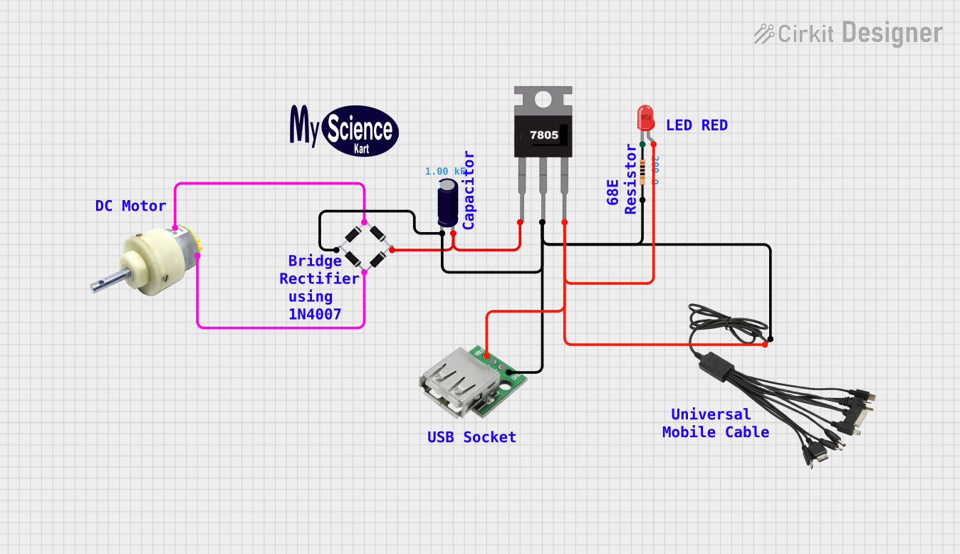
This circuit appears to be a power supply unit with a bridge rectifier connected to a DC gear motor, indicating it is designed to convert AC to DC power for the motor. An electrolytic capacitor is used for smoothing the DC output, and a 7805 voltage regulator is included to provide a stable 5V output. Additionally, there is an LED with a series resistor, likely serving as a power indicator light.
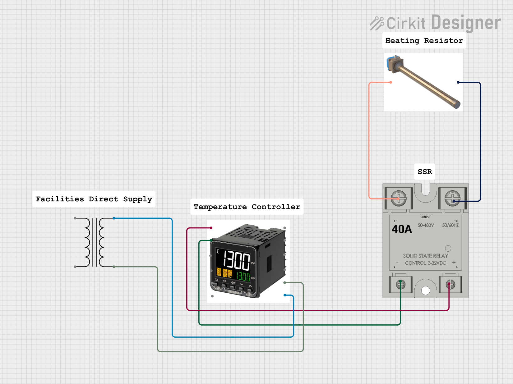
This circuit is a temperature control system that uses a temperature controller to regulate a heating titanium resistor via a solid-state relay (SSR). The power transformer supplies the necessary voltage to the temperature controller, which in turn controls the SSR to manage the heating element.
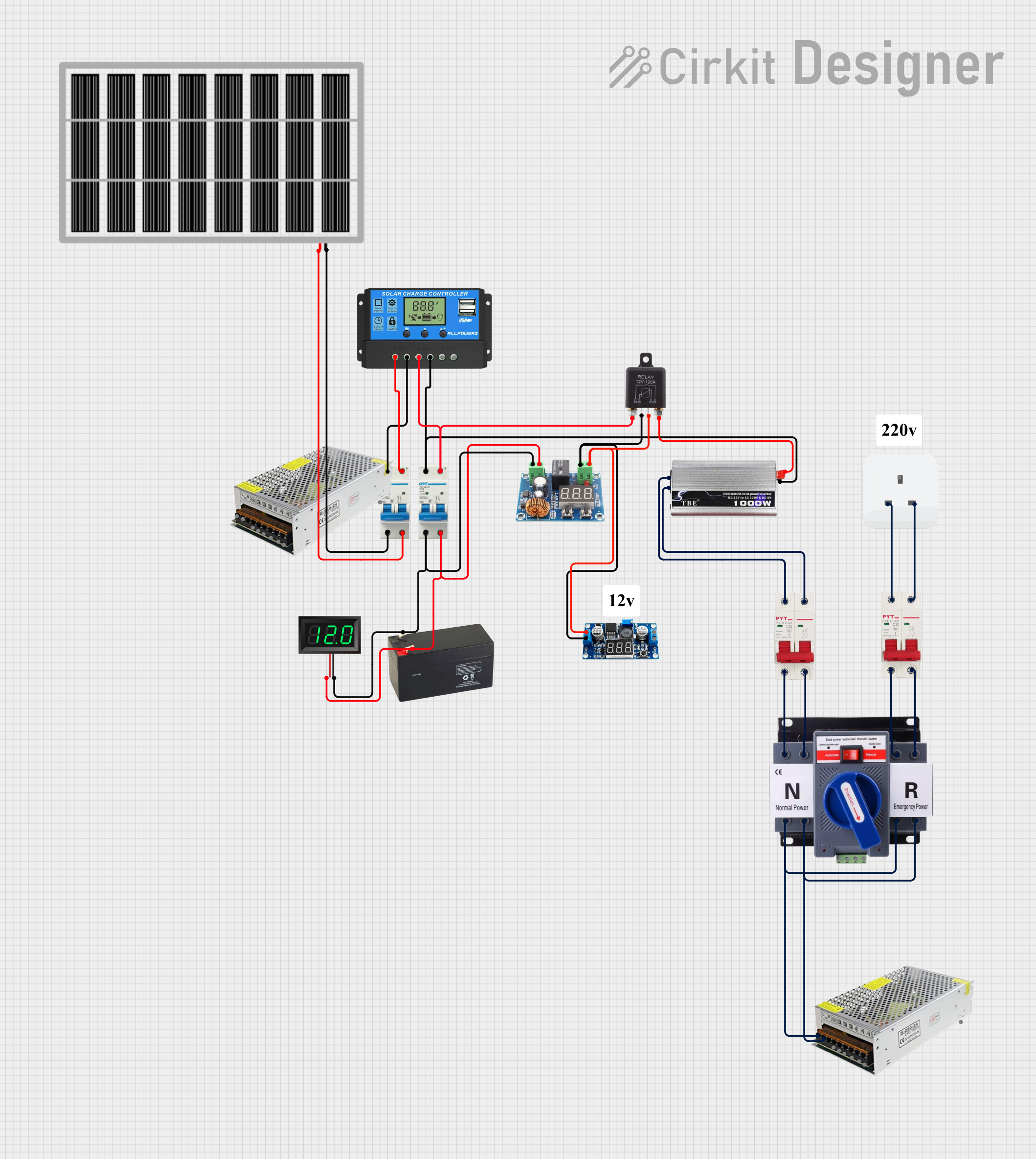
This circuit is a solar power management system that integrates a solar panel, battery, and inverter to provide a stable 12V DC and 220V AC output. It includes automatic transfer switches (ATS) and circuit breakers for safety and reliability, as well as a low voltage disconnect to protect the battery from deep discharge.
The following table outlines the key technical specifications of the Fotek SSR DC-DC:
Parameter
Value
Manufacturer
Fotek
Part ID
Not specified
Input Control Voltage
3-32 V DC
Output Voltage Range
5-220 V DC
Maximum Output Current
40 A
Switching Speed
≤ 10 ms
Isolation Voltage
≥ 2500 V AC
Operating Temperature
-30°C to +80°C
Mounting Type
Panel-mounted
Weight
~100 g
Pin Configuration and Descriptions
The SSR DC-DC typically has four terminals. The table below describes each terminal:
Pin Number
Label
Description
1
+ (Input)
Positive terminal for the control signal (3-32 V DC).
2
- (Input)
Negative terminal for the control signal (ground).
3
+ (Load)
Positive terminal for the DC load. Connect to the positive side of the load.
4
- (Load)
Negative terminal for the DC load. Connect to the negative side of the load.
Usage Instructions
How to Use the SSR DC-DC in a Circuit
Control Signal Connection:
Connect the positive control signal (3-32 V DC) to the + (Input) terminal.
Connect the ground of the control signal to the - (Input) terminal.
Load Connection:
Connect the positive side of the DC load to the + (Load) terminal.
Connect the negative side of the DC load to the - (Load) terminal.
Power Supply:
Ensure the load voltage and current do not exceed the SSR's rated output voltage (5-220 V DC) and current (40 A).
Mounting:
Secure the SSR to a heat sink or panel to ensure proper heat dissipation during operation.
Testing:
Apply the control signal voltage to the input terminals. The SSR should switch the load on or off depending on the control signal.
Important Considerations and Best Practices
Heat Dissipation: Use a heat sink or cooling fan if the SSR operates near its maximum current rating to prevent overheating.
Isolation: Ensure proper electrical isolation between the control and load circuits to avoid damage.
Polarity: Observe correct polarity for both the control signal and load connections.
Surge Protection: Use a flyback diode across inductive loads (e.g., motors) to protect the SSR from voltage spikes.
Testing: Avoid testing the SSR with a multimeter in continuity mode, as it may not provide accurate results for solid-state devices.
Example: Connecting the SSR DC-DC to an Arduino UNO
The SSR DC-DC can be controlled using an Arduino UNO. Below is an example circuit and code:
Circuit Description
Connect the Arduino's digital output pin (e.g., pin 9) to the + (Input) terminal of the SSR.
Connect the Arduino's ground (GND) to the - (Input) terminal of the SSR.
Connect the DC load to the + (Load) and - (Load) terminals of the SSR.
Arduino Code
// Example code to control an SSR DC-DC with an Arduino UNO
// This code toggles the SSR on and off every 1 second.

#define SSR_PIN 9  // Define the Arduino pin connected to the SSR input

void setup() {
  pinMode(SSR_PIN, OUTPUT);  // Set the SSR pin as an output
}

void loop() {
  digitalWrite(SSR_PIN, HIGH);  // Turn the SSR on (control signal HIGH)
  delay(1000);                  // Wait for 1 second
  digitalWrite(SSR_PIN, LOW);   // Turn the SSR off (control signal LOW)
  delay(1000);                  // Wait for 1 second
}
Troubleshooting and FAQs
Common Issues and Solutions
Issue
Possible Cause
Solution
SSR does not switch the load
- Control signal voltage is too low or absent.
- Ensure the control signal is within the 3-32 V DC range.
- Incorrect wiring of control or load terminals.
- Double-check the wiring and polarity.
Load remains on even when SSR is off
- Leakage current through the SSR.
- Use a load resistor to dissipate leakage current if necessary.
SSR overheats during operation
- Load current exceeds the SSR's maximum rating.
- Reduce the load current or use a higher-rated SSR.
- Inadequate heat dissipation.
- Attach a heat sink or cooling fan to the SSR.
Arduino cannot control the SSR
- Arduino output voltage is insufficient to trigger the SSR.
- Use a transistor or MOSFET to amplify the Arduino's output signal.
FAQs
Can the SSR DC-DC be used with AC loads?
No, this SSR is designed specifically for DC loads. For AC loads, use an AC-AC or DC-AC SSR.
What happens if the control signal exceeds 32 V DC?
Exceeding the control voltage range may damage the SSR. Always stay within the specified range.
Is the SSR polarity-sensitive?
Yes, both the control and load terminals are polarity-sensitive. Incorrect polarity may damage the SSR or prevent it from functioning.
Can I use the SSR without a heat sink?
For low-current applications, a heat sink may not be necessary. However, for high-current loads, a heat sink is essential to prevent overheating.
By following this documentation, you can effectively integrate the Fotek SSR DC-DC into your projects and ensure reliable operation.



 Open Project in Cirkit Designer