How to Use AC SPD: Examples, Pinouts, and Specs
Introduction
An AC Surge Protective Device (SPD) is designed to protect electrical equipment from voltage spikes and surges in alternating current (AC) systems. These surges are typically caused by lightning strikes, power fluctuations, or switching operations in the power grid. By diverting excess voltage to the ground, the AC SPD ensures the safety and longevity of connected devices.
Explore Projects Built with AC SPD

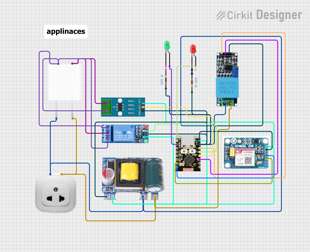
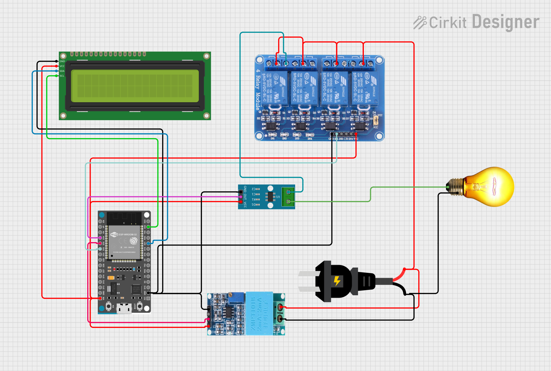
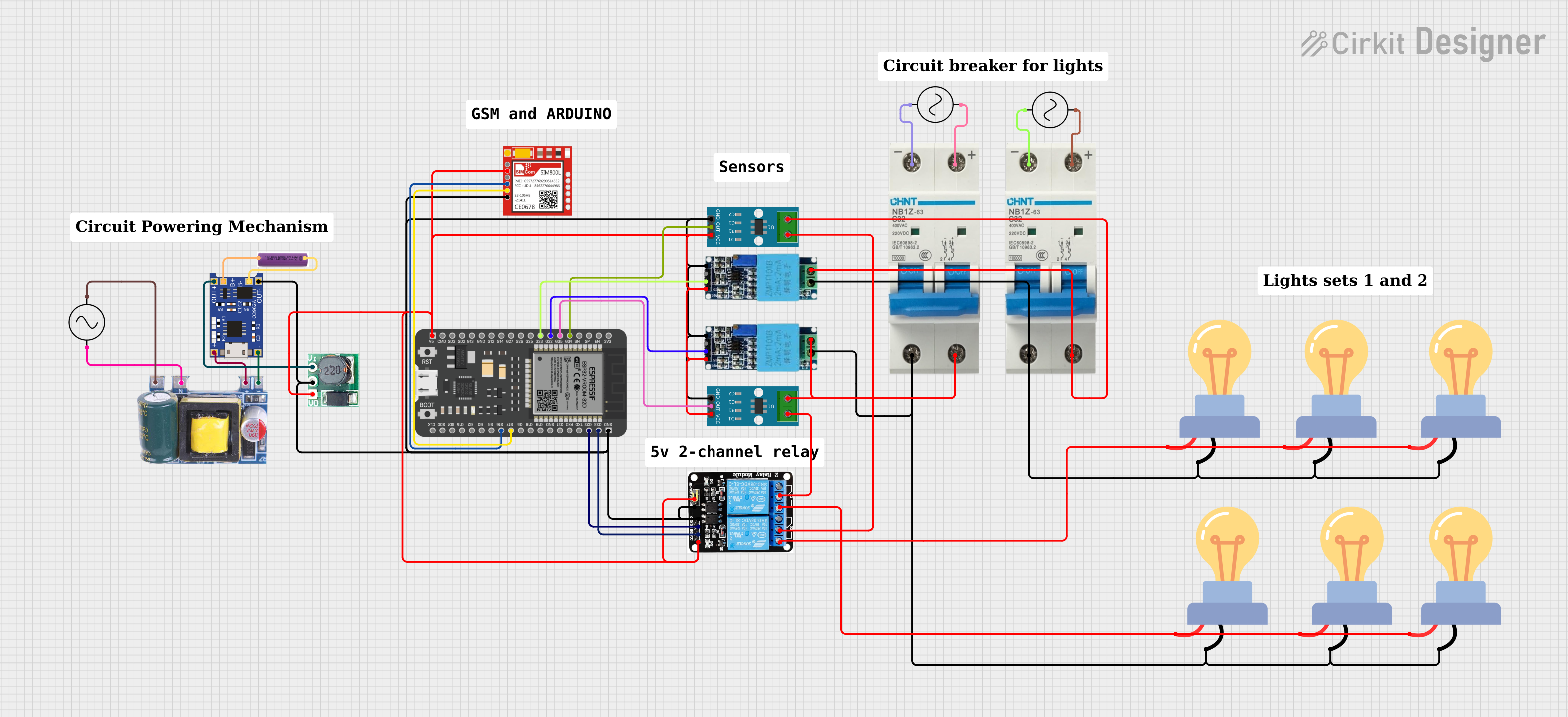
Explore Projects Built with AC SPD
Common Applications and Use Cases
- Protection of residential, commercial, and industrial electrical systems.
- Safeguarding sensitive electronic equipment such as computers, servers, and medical devices.
- Use in power distribution panels, control panels, and communication systems.
- Protection against transient overvoltages in renewable energy systems (e.g., solar inverters).
Technical Specifications
Key Technical Details
| Parameter | Value/Range |
|---|---|
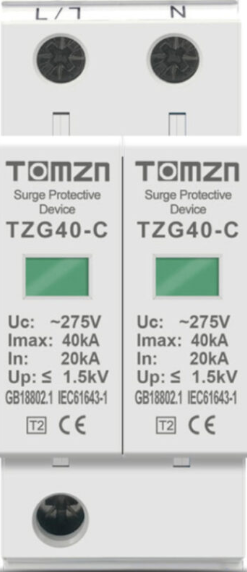
| Nominal Voltage (Un) | 120V, 230V, 400V AC (varies by model) |
| Maximum Continuous Voltage (Uc) | 150V, 275V, 440V AC |
| Surge Current Capacity (Imax) | 10kA to 100kA (8/20 µs waveform) |
| Voltage Protection Level (Up) | ≤ 1.5kV to ≤ 4kV |
| Response Time | < 25 nanoseconds |
| Operating Temperature Range | -40°C to +85°C |
| Enclosure Rating | IP20 to IP65 (depending on model) |
| Standards Compliance | IEC 61643-11, UL 1449 |
Pin Configuration and Descriptions
| Pin/Terminal | Description |
|---|---|
| L (Line) | Connects to the live wire of the AC system. |
| N (Neutral) | Connects to the neutral wire of the AC system. |
| PE (Earth) | Connects to the protective earth/ground wire. |
Usage Instructions
How to Use the Component in a Circuit
- Placement in the Circuit: Install the AC SPD as close as possible to the equipment or distribution panel it is protecting. It is typically connected in parallel with the load.
- Wiring:
- Connect the
Lterminal to the live wire of the AC system. - Connect the
Nterminal to the neutral wire. - Connect the
PEterminal to the ground wire for proper surge diversion.
- Connect the
- Fuse Protection: Use a fuse or circuit breaker in series with the SPD to protect it from overcurrent conditions.
- Grounding: Ensure a low-impedance connection to the ground for effective surge suppression.
Important Considerations and Best Practices
- Voltage Rating: Select an SPD with a nominal voltage (Un) and maximum continuous voltage (Uc) suitable for your AC system.
- Surge Current Capacity: Choose an SPD with a surge current capacity (Imax) that matches the expected surge levels in your environment.
- Periodic Inspection: Regularly inspect the SPD for signs of wear or damage, especially after a known surge event.
- Indicator Monitoring: Many SPDs include a status indicator (e.g., LED) to show whether the device is operational. Replace the SPD if the indicator shows failure.
Example: Connecting to an Arduino UNO
While an AC SPD is not directly connected to an Arduino UNO, it can protect the power supply feeding the Arduino. For example, if the Arduino is powered via an AC adapter, the SPD can be installed at the AC input to safeguard the adapter and, indirectly, the Arduino.
// Example Arduino code to monitor a power supply's status
// This assumes a voltage sensor is used to detect power supply issues.

const int sensorPin = A0;  // Analog pin connected to the voltage sensor
const int threshold = 500; // Threshold value for detecting power issues

void setup() {
  Serial.begin(9600); // Initialize serial communication
  pinMode(sensorPin, INPUT); // Set the sensor pin as input
}

void loop() {
  int sensorValue = analogRead(sensorPin); // Read the sensor value
  if (sensorValue < threshold) {
    Serial.println("Warning: Power supply issue detected!");
    // Take appropriate action, such as shutting down sensitive equipment
  } else {
    Serial.println("Power supply is stable.");
  }
  delay(1000); // Wait for 1 second before the next reading
}
Troubleshooting and FAQs
Common Issues Users Might Face
SPD Not Functioning After a Surge Event:
- Cause: The SPD may have reached the end of its life after handling a large surge.
- Solution: Replace the SPD immediately to maintain protection.
Frequent Tripping of Circuit Breaker:
- Cause: Incorrect wiring or an SPD with a lower voltage rating than the system.
- Solution: Verify the wiring and ensure the SPD's voltage rating matches the AC system.
No Status Indicator Light:
- Cause: The SPD may have failed or the indicator light is damaged.
- Solution: Test the SPD with a multimeter or replace it if necessary.
Poor Surge Protection Performance:
- Cause: Improper grounding or a damaged SPD.
- Solution: Check the grounding connection and replace the SPD if needed.
Solutions and Tips for Troubleshooting
- Always disconnect power before inspecting or replacing the SPD.
- Use a multimeter to verify continuity and proper connections.
- Ensure the SPD is compliant with the standards required for your region (e.g., IEC 61643-11, UL 1449).
- Consult the manufacturer's documentation for model-specific troubleshooting steps.
By following these guidelines, you can ensure the effective operation of your AC SPD and protect your electrical systems from damaging surges.