How to Use MAX17048 Breakout: Examples, Pinouts, and Specs
Introduction
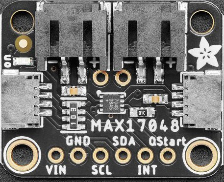
The MAX17048 Breakout (Adafruit Part ID: 5580) is a compact and efficient breakout board featuring the MAX17048 battery fuel gauge IC. This component provides accurate battery state-of-charge (SoC) information using a simple I2C interface, making it ideal for battery-powered projects. The MAX17048 eliminates the need for complex battery characterization or calibration, offering a plug-and-play solution for monitoring lithium-ion (Li-ion) or lithium-polymer (LiPo) batteries.
Explore Projects Built with MAX17048 Breakout


Explore Projects Built with MAX17048 Breakout
Common Applications and Use Cases
- Battery-powered IoT devices
- Wearable electronics
- Portable medical devices
- Robotics and drones
- Power banks and battery management systems
Technical Specifications
The MAX17048 Breakout is designed for ease of use and integration. Below are its key technical details:
Key Specifications
| Parameter | Value |
|---|---|
| Input Voltage Range | 2.5V to 4.5V |
| Communication Interface | I2C |
| Operating Current | 50 µA (typical) |
| Battery Chemistry | Lithium-ion (Li-ion) or Lithium-polymer |
| State-of-Charge Accuracy | ±1% |
| Operating Temperature Range | -40°C to +85°C |
| Dimensions | 0.7" x 0.7" (17.8mm x 17.8mm) |
Pin Configuration and Descriptions
The MAX17048 Breakout has six pins, as detailed below:
| Pin Name | Description |
|---|---|
| VIN | Power input (2.5V to 5.5V). Connect to the power source. |
| GND | Ground. Connect to the ground of the circuit. |
| SCL | I2C clock line. Connect to the SCL pin of the microcontroller. |
| SDA | I2C data line. Connect to the SDA pin of the microcontroller. |
| ALERT | Open-drain interrupt output. Can be used to signal low battery conditions. |
| BAT | Battery input. Connect directly to the positive terminal of the battery. |
Usage Instructions
The MAX17048 Breakout is straightforward to use in a circuit. Follow the steps below to integrate it into your project:
Connecting the MAX17048 Breakout
- Power Supply: Connect the VIN pin to a 3.3V or 5V power source and the GND pin to ground.
- Battery Connection: Connect the BAT pin to the positive terminal of the Li-ion or LiPo battery.
- I2C Interface: Connect the SCL and SDA pins to the corresponding I2C pins on your microcontroller.
- Optional ALERT Pin: If you want to use the ALERT feature, connect the ALERT pin to a GPIO pin on your microcontroller.
Important Considerations
- Ensure the battery voltage is within the 2.5V to 4.5V range for accurate readings.
- Use pull-up resistors (typically 4.7kΩ) on the SCL and SDA lines if your microcontroller does not have internal pull-ups.
- Avoid connecting the BAT pin to a power supply; it is designed specifically for battery input.
Example Code for Arduino UNO
Below is an example Arduino sketch to read the battery state-of-charge using the MAX17048 Breakout:
#include <Wire.h>

// MAX17048 I2C address
#define MAX17048_ADDRESS 0x36

void setup() {
  Wire.begin(); // Initialize I2C communication
  Serial.begin(9600); // Start serial communication for debugging

  // Check if the MAX17048 is connected
  Wire.beginTransmission(MAX17048_ADDRESS);
  if (Wire.endTransmission() != 0) {
    Serial.println("MAX17048 not detected. Check connections.");
    while (1); // Halt execution if the device is not found
  }
  Serial.println("MAX17048 detected successfully.");
}

void loop() {
  float soc = readStateOfCharge(); // Read battery state-of-charge
  Serial.print("Battery State-of-Charge: ");
  Serial.print(soc);
  Serial.println("%");
  delay(1000); // Wait 1 second before the next reading
}

float readStateOfCharge() {
  Wire.beginTransmission(MAX17048_ADDRESS);
  Wire.write(0x04); // Register address for state-of-charge
  Wire.endTransmission(false); // Send repeated start condition
  Wire.requestFrom(MAX17048_ADDRESS, 2); // Request 2 bytes of data

  if (Wire.available() < 2) {
    return -1; // Return -1 if data is not available
  }

  uint16_t socRaw = (Wire.read() << 8) | Wire.read(); // Combine MSB and LSB
  return socRaw / 256.0; // Convert to percentage
}
Notes on the Code
- The
readStateOfCharge()function reads the state-of-charge register (0x04) and converts the raw data into a percentage. - Ensure the I2C address (0x36) matches the default address of the MAX17048. If the address is different, update it in the code.
Troubleshooting and FAQs
Common Issues
MAX17048 Not Detected
- Cause: Incorrect wiring or I2C address mismatch.
- Solution: Verify the connections to the SCL and SDA pins. Ensure pull-up resistors are present if required. Check that the I2C address in the code matches the device's address.
Incorrect State-of-Charge Readings
- Cause: Battery voltage outside the supported range or poor battery connection.
- Solution: Ensure the battery voltage is between 2.5V and 4.5V. Check the BAT pin connection.
ALERT Pin Not Functioning
- Cause: ALERT pin not configured or monitored in the code.
- Solution: Configure the ALERT pin as an input on the microcontroller and monitor its state.
FAQs
Q: Can the MAX17048 Breakout monitor multiple batteries?
A: No, the MAX17048 is designed to monitor a single Li-ion or LiPo battery.
Q: Do I need to calibrate the MAX17048?
A: No, the MAX17048 uses Maxim's ModelGauge algorithm, which eliminates the need for calibration.
Q: Can I use the MAX17048 with a 5V microcontroller?
A: Yes, the breakout board is compatible with both 3.3V and 5V logic levels.
Q: What happens if the battery voltage drops below 2.5V?
A: The MAX17048 may provide inaccurate readings or stop functioning. Ensure the battery voltage remains within the specified range.