Cirkit Designer
Your all-in-one circuit design IDE
Home /
Component Documentation
How to Use Pressure Transducer: Examples, Pinouts, and Specs
Introduction
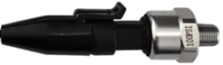
A pressure transducer is a device that converts pressure into an electrical signal for measurement and control purposes. These devices are essential in various applications, including industrial automation, automotive systems, and medical equipment. By providing accurate pressure readings, pressure transducers enable precise control and monitoring of systems, ensuring safety and efficiency.
Explore Projects Built with Pressure Transducer
Pressure Monitoring System with Voltmeter and Power Supply
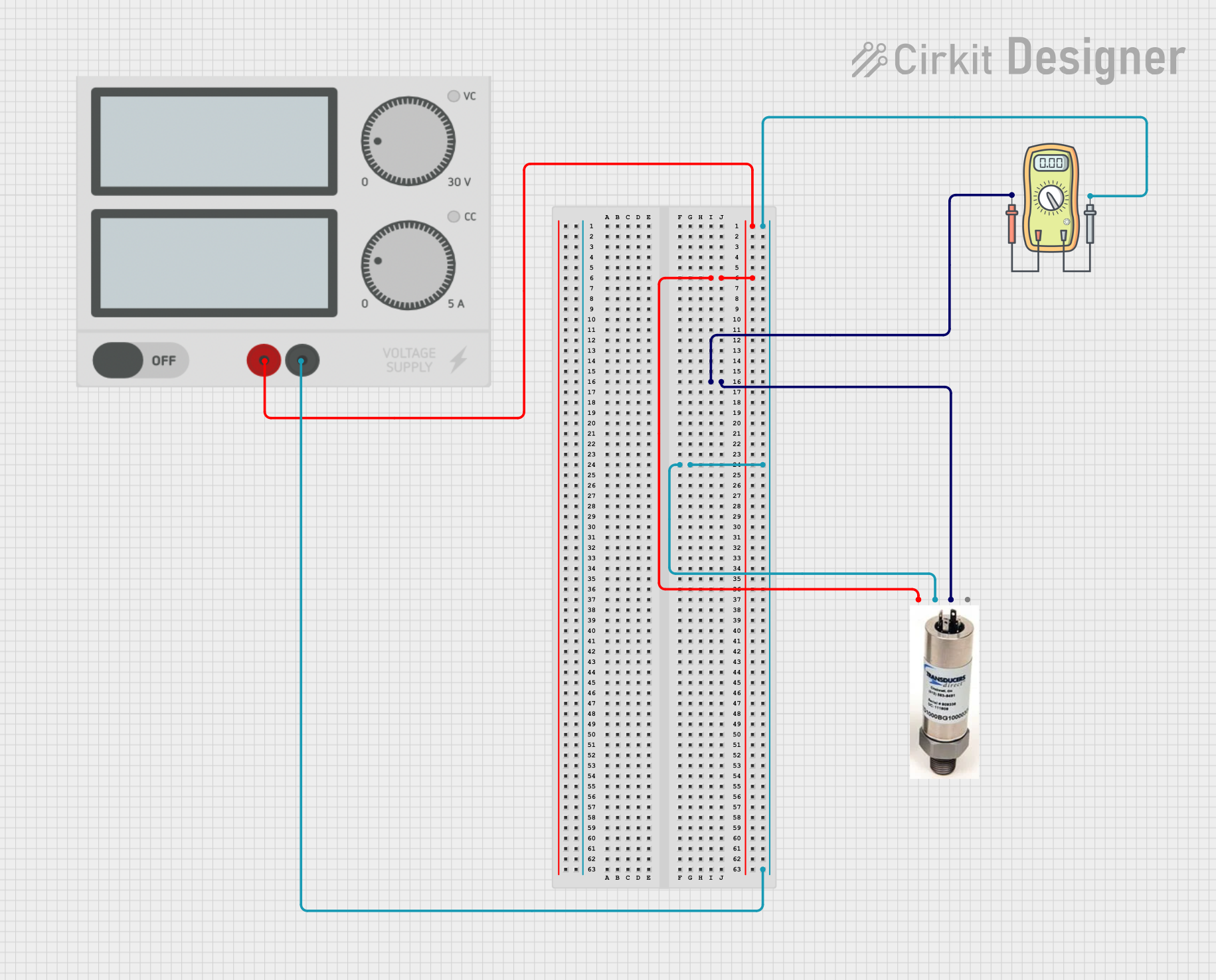
This circuit measures the output voltage of a pressure transducer using a voltmeter. The pressure transducer is powered by a power supply, and its output voltage is connected to the voltmeter for measurement.
ESP32-Controlled Pressure Monitoring System with ADS1115 and Darlington Transistor Switching
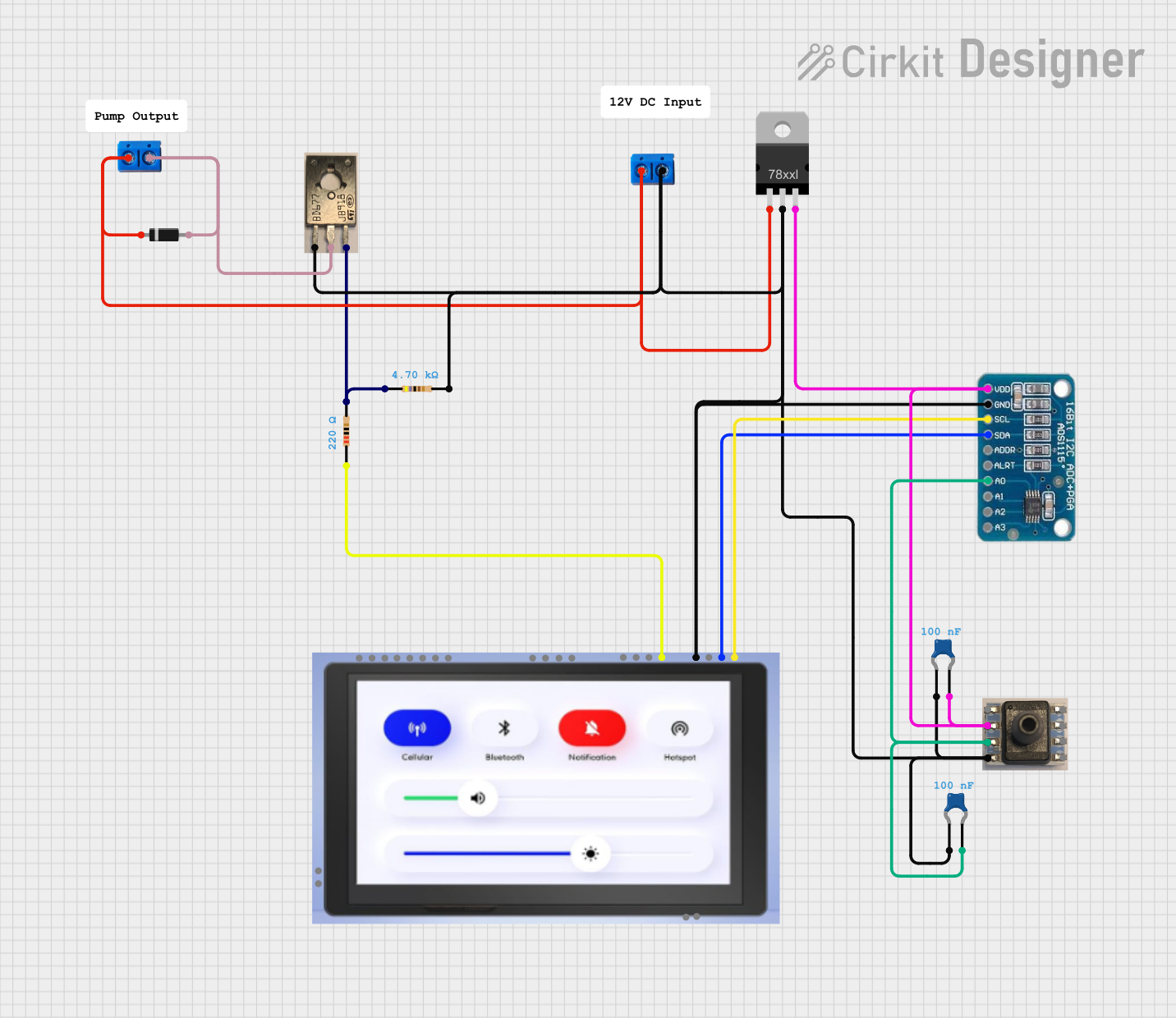
This circuit is designed to measure pressure using a transducer, convert the analog signal to digital with an ADS1115 ADC, and process and display the data on an ESP32 microcontroller with a 7-inch screen. It includes power regulation and filtering, as well as a Darlington transistor for load control.
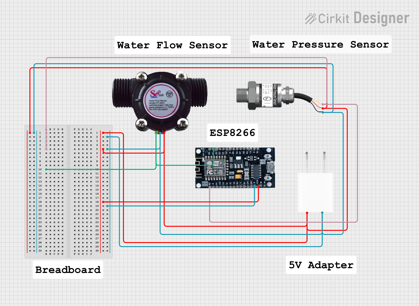
Wi-Fi Enabled Water Monitoring System with ESP8266
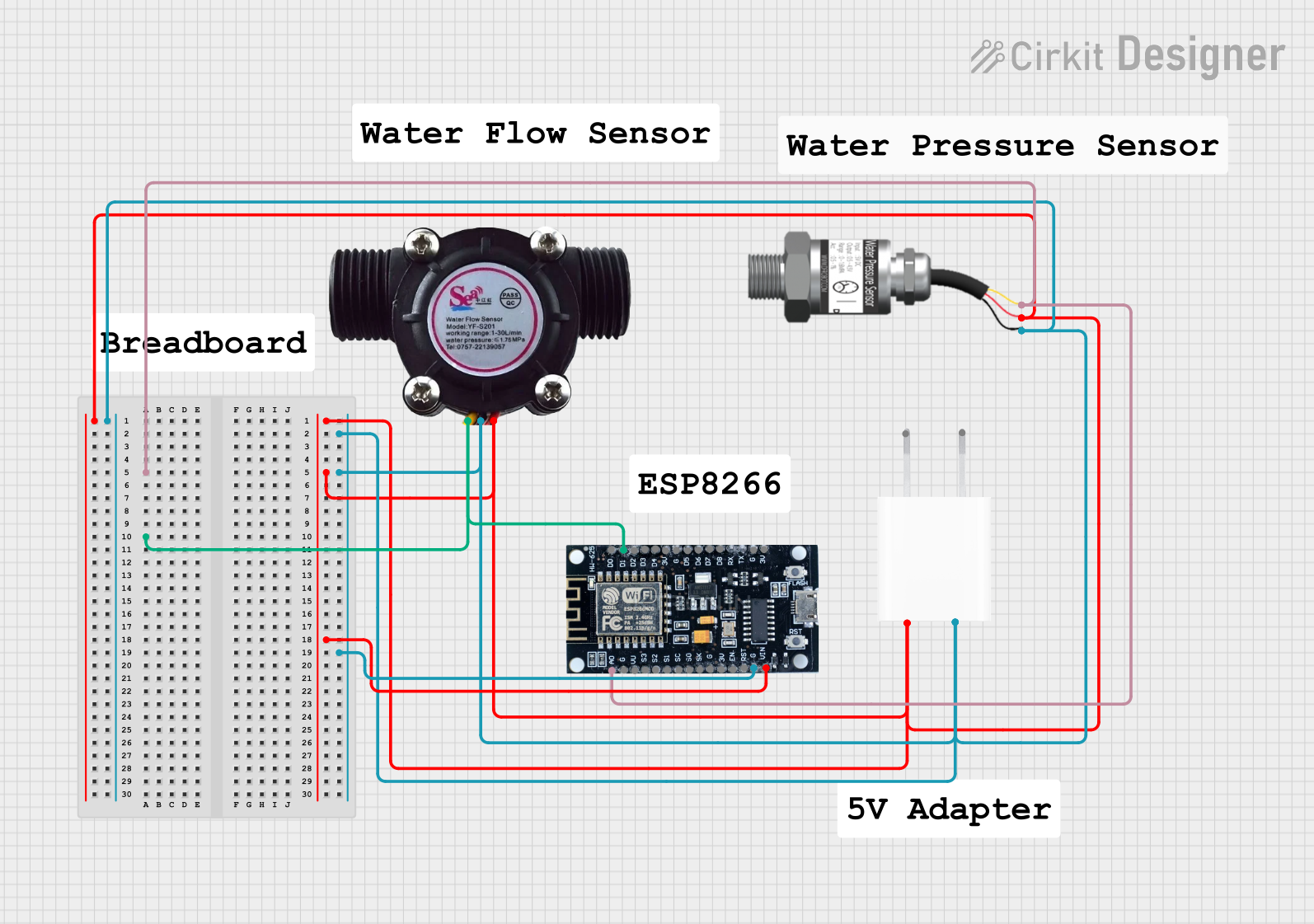
This circuit monitors water pressure and flow using a Gravity analog water pressure sensor and a water flow sensor, respectively. The sensors are powered by a 5V adapter and their signals are read by an ESP8266 microcontroller, which can process and transmit the data for further use.
Wi-Fi Enabled Water Monitoring System with ESP8266
This circuit monitors water pressure and flow using a Gravity analog water pressure sensor and a water flow sensor, respectively. The sensors are powered by a 5V adapter and their signals are read by an ESP8266 microcontroller, which can process and transmit the data for further use.
Explore Projects Built with Pressure Transducer
Pressure Monitoring System with Voltmeter and Power Supply
This circuit measures the output voltage of a pressure transducer using a voltmeter. The pressure transducer is powered by a power supply, and its output voltage is connected to the voltmeter for measurement.
ESP32-Controlled Pressure Monitoring System with ADS1115 and Darlington Transistor Switching
This circuit is designed to measure pressure using a transducer, convert the analog signal to digital with an ADS1115 ADC, and process and display the data on an ESP32 microcontroller with a 7-inch screen. It includes power regulation and filtering, as well as a Darlington transistor for load control.
Wi-Fi Enabled Water Monitoring System with ESP8266
This circuit monitors water pressure and flow using a Gravity analog water pressure sensor and a water flow sensor, respectively. The sensors are powered by a 5V adapter and their signals are read by an ESP8266 microcontroller, which can process and transmit the data for further use.
Technical Specifications
Key Technical Details
| Parameter | Value |
|---|---|
| Supply Voltage | 5V DC |
| Output Signal | 0.5V to 4.5V (analog) |
| Pressure Range | 0 to 100 psi |
| Accuracy | ±1% of full scale |
| Operating Temperature | -40°C to 125°C |
| Response Time | < 1 ms |
| Electrical Connection | 3-pin (Vcc, GND, Signal) |
Pin Configuration and Descriptions
| Pin Number | Pin Name | Description |
|---|---|---|
| 1 | Vcc | Supply voltage (5V DC) |
| 2 | GND | Ground |
| 3 | Signal | Analog output signal (0.5V to 4.5V) |
Usage Instructions
How to Use the Component in a Circuit
- Power Supply: Connect the Vcc pin to a 5V DC power supply.
- Ground Connection: Connect the GND pin to the ground of the power supply.
- Signal Output: Connect the Signal pin to an analog input pin of a microcontroller (e.g., Arduino UNO).
Important Considerations and Best Practices
- Power Supply: Ensure a stable 5V DC power supply to avoid inaccurate readings.
- Calibration: Calibrate the transducer according to the manufacturer's instructions for precise measurements.
- Temperature Effects: Be aware of the operating temperature range to prevent damage and ensure accurate readings.
- Signal Conditioning: Use appropriate signal conditioning techniques if the output signal needs to be processed further.
Example Circuit with Arduino UNO
// Example code to read pressure from a pressure transducer
// connected to an Arduino UNO

const int pressurePin = A0; // Analog pin connected to Signal pin of transducer
float pressureValue = 0;    // Variable to store the pressure value

void setup() {
  Serial.begin(9600); // Initialize serial communication at 9600 baud rate
}

void loop() {
  int sensorValue = analogRead(pressurePin); // Read the analog value
  pressureValue = (sensorValue / 1023.0) * 100; // Convert to pressure (0-100 psi)

  // Print the pressure value to the Serial Monitor
  Serial.print("Pressure: ");
  Serial.print(pressureValue);
  Serial.println(" psi");

  delay(1000); // Wait for 1 second before the next reading
}
Troubleshooting and FAQs
Common Issues Users Might Face
Inaccurate Readings:
- Solution: Ensure proper calibration and stable power supply. Check for any temperature variations that might affect the readings.
No Output Signal:
- Solution: Verify the connections, especially the Vcc and GND pins. Ensure the transducer is receiving the correct supply voltage.
Fluctuating Readings:
- Solution: Use capacitors for filtering noise in the power supply. Ensure the signal wire is not running parallel to high-power lines.
Solutions and Tips for Troubleshooting
- Check Connections: Ensure all connections are secure and correct.
- Stable Power Supply: Use a regulated power supply to avoid fluctuations.
- Calibration: Regularly calibrate the transducer to maintain accuracy.
- Environmental Factors: Consider the operating environment and protect the transducer from extreme conditions.
By following this documentation, users can effectively integrate and utilize a pressure transducer in their projects, ensuring accurate pressure measurements and reliable system performance.