
How to Use 2x5 Shrouded Male Header (2.54 mm): Examples, Pinouts, and Specs
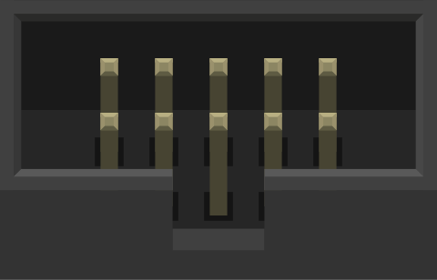
 Design with 2x5 Shrouded Male Header (2.54 mm) in Cirkit Designer
Introduction
The 2x5 Shrouded Male Header is a connector featuring two rows of five pins, with a standard 2.54 mm (0.1 inch) pin spacing. Its shrouded design ensures proper alignment during mating and prevents accidental disconnections, making it a reliable choice for secure and durable connections in electronic circuits. This component is widely used in applications requiring compact, robust, and repeatable connections, such as programming interfaces, communication ports, and modular PCB designs.
Explore Projects Built with 2x5 Shrouded Male Header (2.54 mm)
 Open Project in Cirkit Designer
 Open Project in Cirkit Designer
 Open Project in Cirkit Designer
 Open Project in Cirkit Designer
Explore Projects Built with 2x5 Shrouded Male Header (2.54 mm)
Open Project in Cirkit DesignerOpen Project in Cirkit DesignerOpen Project in Cirkit DesignerOpen Project in Cirkit DesignerCommon Applications
- Microcontroller Programming Interfaces: Commonly used for ISP (In-System Programming) headers.
- Communication Ports: Ideal for UART, SPI, or I2C connections.
- Modular PCB Connections: Used to connect stacked or adjacent PCBs.
- Prototyping and Development Boards: Provides a reliable interface for debugging and testing.
Technical Specifications
Key Technical Details
| Parameter | Value |
|---|---|
| Pin Count | 10 (2 rows of 5 pins) |
| Pin Spacing | 2.54 mm (0.1 inch) |
| Current Rating | Typically 3 A per pin |
| Voltage Rating | Typically 250 V |
| Operating Temperature | -40°C to +105°C |
| Material (Housing) | Thermoplastic, UL94V-0 rated |
| Material (Pins) | Gold-plated or tin-plated copper alloy |
| Mounting Style | Through-hole or surface mount |
Pin Configuration and Descriptions
The 2x5 shrouded male header has two rows of pins, typically labeled as Row A and Row B. The pin numbering starts from the top-left corner (Pin 1) and alternates between rows.
| Pin Number | Row | Description (Typical Use) |
|---|---|---|
| 1 | A | Signal or Power (e.g., VCC) |
| 2 | B | Ground (GND) |
| 3 | A | Signal (e.g., SPI MOSI) |
| 4 | B | Signal (e.g., SPI MISO) |
| 5 | A | Signal (e.g., SPI SCK) |
| 6 | B | Ground (GND) |
| 7 | A | Signal (e.g., Reset) |
| 8 | B | Signal (e.g., Chip Select) |
| 9 | A | Reserved or Custom Signal |
| 10 | B | Reserved or Custom Signal |
Note: Pin assignments may vary depending on the application. Always refer to the specific circuit or device documentation.
Usage Instructions
How to Use the Component in a Circuit
- Mounting the Header:
- For through-hole headers, insert the pins into the PCB holes and solder them securely.
- For surface-mount headers, align the pins with the PCB pads and solder them using reflow or manual soldering techniques.
- Mating with a Connector:
- Use a compatible 2x5 female connector or ribbon cable with a matching shroud.
- Ensure proper alignment using the shroud's keying feature to avoid reversed connections.
- Wiring:
- Connect the pins to the appropriate signals or power lines as per your circuit design.
- Double-check the pinout to prevent miswiring.
Important Considerations and Best Practices
- Alignment: Always ensure the connector is properly aligned before mating to avoid damaging the pins.
- Soldering: Use appropriate soldering techniques to ensure a reliable connection without cold joints.
- Current and Voltage Ratings: Do not exceed the specified current and voltage ratings to prevent overheating or damage.
- Keying Feature: Take advantage of the shroud's keying feature to prevent reversed connections.
- Cleaning: After soldering, clean the PCB to remove flux residues that may cause corrosion or short circuits.
Example: Connecting to an Arduino UNO
The 2x5 shrouded male header is commonly used for ISP programming of microcontrollers, including the Arduino UNO. Below is an example of how to connect the header for SPI communication.
Wiring Diagram
| Header Pin | Arduino UNO Pin |
|---|---|
| Pin 1 (VCC) | 5V |
| Pin 2 (GND) | GND |
| Pin 3 (MOSI) | D11 |
| Pin 4 (MISO) | D12 |
| Pin 5 (SCK) | D13 |
| Pin 7 (Reset) | Reset |
Example Code
// Example code to communicate with an SPI device using the 2x5 header
#include <SPI.h>

void setup() {
  // Initialize SPI communication
  SPI.begin();
  Serial.begin(9600);
  Serial.println("SPI Communication Initialized");
}

void loop() {
  // Example: Send data to an SPI device
  digitalWrite(SS, LOW); // Select the SPI device
  SPI.transfer(0x42);    // Send a byte (0x42) to the device
  digitalWrite(SS, HIGH); // Deselect the SPI device

  delay(1000); // Wait for 1 second
}
Note: Ensure the
SSpin is correctly defined for your specific SPI device.
Troubleshooting and FAQs
Common Issues
Misaligned Connection:
- Problem: The connector does not fit or the circuit does not work.
- Solution: Check the alignment of the shroud and ensure the keying feature is used correctly.
Cold Solder Joints:
- Problem: Intermittent or unreliable connections.
- Solution: Re-solder the pins using proper soldering techniques and ensure good wetting.
Overheating:
- Problem: The header or connected components become hot.
- Solution: Verify that the current and voltage ratings are not exceeded.
Signal Interference:
- Problem: Data corruption or communication errors.
- Solution: Use proper grounding and minimize noise by keeping signal traces short.
FAQs
Q: Can I use this header for high-speed signals?
- A: Yes, but ensure proper PCB design practices, such as impedance matching and minimizing trace lengths, to maintain signal integrity.
Q: Is the shroud removable?
- A: No, the shroud is typically fixed and designed to ensure proper alignment and protection.
Q: Can I use this header with a ribbon cable?
- A: Yes, it is compatible with 2x5 IDC ribbon cables for easy and reliable connections.
Q: What tools are recommended for soldering this header?
- A: Use a fine-tipped soldering iron and high-quality solder. A flux pen can help ensure clean and reliable joints.
By following this documentation, you can effectively integrate the 2x5 Shrouded Male Header into your electronic projects with confidence and reliability.