How to Use Gameboy Zero Headphone Jack: Examples, Pinouts, and Specs
Introduction
The Gameboy Zero Headphone Jack is a compact and durable audio connector designed specifically for the Gameboy Zero project. It enables seamless audio output to headphones or external speakers, enhancing the gaming experience with high-quality sound. This component is essential for retro gaming enthusiasts who want to integrate modern audio functionality into their custom Gameboy Zero builds.
Explore Projects Built with Gameboy Zero Headphone Jack

Explore Projects Built with Gameboy Zero Headphone Jack
Common Applications and Use Cases
- Audio output for Gameboy Zero handheld consoles.
- Integration into custom retro gaming projects.
- Use in DIY audio devices requiring a 3.5mm headphone jack.
- Connecting external speakers or headphones for enhanced sound quality.
Technical Specifications
The Gameboy Zero Headphone Jack is a 3.5mm TRRS (Tip-Ring-Ring-Sleeve) connector, supporting stereo audio output and optional microphone input. Below are the key technical details:
Key Specifications
| Parameter | Value |
|---|---|
| Connector Type | 3.5mm TRRS |
| Audio Channels | Stereo (Left and Right) |
| Voltage Rating | 5V (typical for audio circuits) |
| Current Rating | 500mA (maximum) |
| Mounting Type | Through-hole or PCB-mounted |
| Material | Gold-plated contacts for durability and conductivity |
| Dimensions | 14mm x 6mm x 6mm |
Pin Configuration and Descriptions
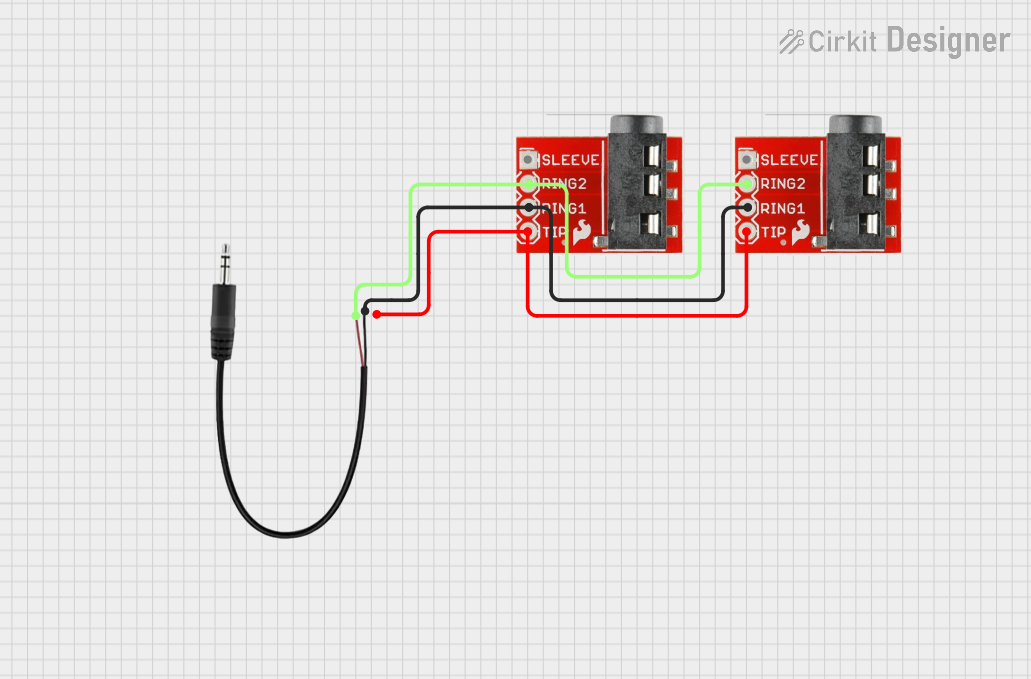
The headphone jack has four pins corresponding to the TRRS configuration. Below is the pinout:
| Pin Number | Name | Description |
|---|---|---|
| 1 | Tip (L) | Left audio channel output |
| 2 | Ring 1 (R) | Right audio channel output |
| 3 | Ring 2 (MIC) | Microphone input (optional, not used in all setups) |
| 4 | Sleeve (GND) | Ground connection |
Usage Instructions
How to Use the Component in a Circuit
- Identify the Pins: Refer to the pin configuration table above to correctly identify the pins for Left (L), Right (R), Microphone (MIC), and Ground (GND).
- Soldering: Mount the headphone jack onto the PCB or connect it using wires. Ensure proper soldering to avoid loose connections.
- Connect to Audio Source:
- For stereo audio output, connect the Tip (L) and Ring 1 (R) pins to the left and right audio channels of your audio source.
- Connect the Sleeve (GND) pin to the ground of your circuit.
- Optional Microphone Input: If your project requires a microphone, connect the Ring 2 (MIC) pin to the microphone input circuit.
- Test the Connection: Plug in headphones or speakers and test the audio output. Adjust the volume as needed.
Important Considerations and Best Practices
- Avoid Short Circuits: Ensure that no solder bridges form between adjacent pins during assembly.
- Use Shielded Cables: For optimal audio quality, use shielded cables to minimize noise and interference.
- Check Compatibility: Verify that the audio source and headphones/speakers are compatible with the 3.5mm TRRS standard.
- Volume Control: If the audio output is too loud or distorted, consider adding a potentiometer or resistor to control the volume.
Arduino UNO Example Code
If you are using the headphone jack with an Arduino UNO for audio output, you can use the following example code to generate a simple tone:
/*
  Example code to generate a tone using Arduino UNO
  and output it through the Gameboy Zero Headphone Jack.
  Connect the Tip (L) or Ring 1 (R) pin to a PWM pin on the Arduino.
  Connect the Sleeve (GND) pin to the Arduino GND.
*/

const int audioPin = 9; // PWM pin connected to the headphone jack

void setup() {
  pinMode(audioPin, OUTPUT); // Set the audio pin as an output
}

void loop() {
  // Generate a 1kHz tone for 500ms
  tone(audioPin, 1000, 500);
  delay(1000); // Wait for 1 second before repeating
}
Note: The
tone()function generates a square wave, which may not produce high-quality audio. For better sound, consider using an external audio DAC.
Troubleshooting and FAQs
Common Issues and Solutions
No Audio Output:
- Cause: Incorrect pin connections or loose solder joints.
- Solution: Double-check the pin connections and ensure proper soldering.
Distorted Audio:
- Cause: Overdriving the audio signal or using unshielded cables.
- Solution: Add a resistor or potentiometer to control the volume. Use shielded cables to reduce noise.
Microphone Not Working:
- Cause: MIC pin not connected or incompatible microphone.
- Solution: Verify the microphone's compatibility and ensure proper connection to the MIC pin.
Intermittent Audio:
- Cause: Poor contact between the headphone jack and the plug.
- Solution: Clean the jack and plug with isopropyl alcohol to remove dirt or oxidation.
FAQs
Q: Can I use this headphone jack with mono audio?
A: Yes, you can connect the Tip (L) pin to the audio source and leave the Ring 1 (R) pin unconnected. Alternatively, you can combine the left and right channels using resistors.
Q: Is this headphone jack compatible with all 3.5mm plugs?
A: The Gameboy Zero Headphone Jack is designed for TRRS plugs but is also compatible with TRS plugs (stereo without microphone).
Q: Can I use this jack for both input and output?
A: While primarily designed for audio output, the MIC pin can be used for input if your circuit supports it.
Q: How do I mount the headphone jack on a PCB?
A: Align the pins with the PCB holes, solder them securely, and ensure the jack is flush with the board for stability.