How to Use Mini Pushbutton Power Switch with Reverse Voltage Protection, SV: Examples, Pinouts, and Specs
Introduction
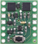
The Mini Pushbutton Power Switch with Reverse Voltage Protection (Pololu #2809) is a compact and efficient electronic switch designed for easy on/off control of low-power circuits. This switch features built-in reverse voltage protection, safeguarding your circuit from accidental damage caused by incorrect power supply connections. Its small size and robust design make it ideal for a wide range of applications, including battery-powered devices, robotics, and DIY electronics projects.
Explore Projects Built with Mini Pushbutton Power Switch with Reverse Voltage Protection, SV


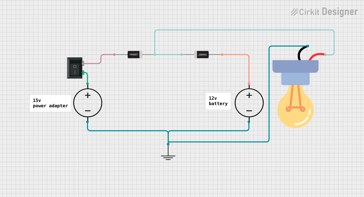
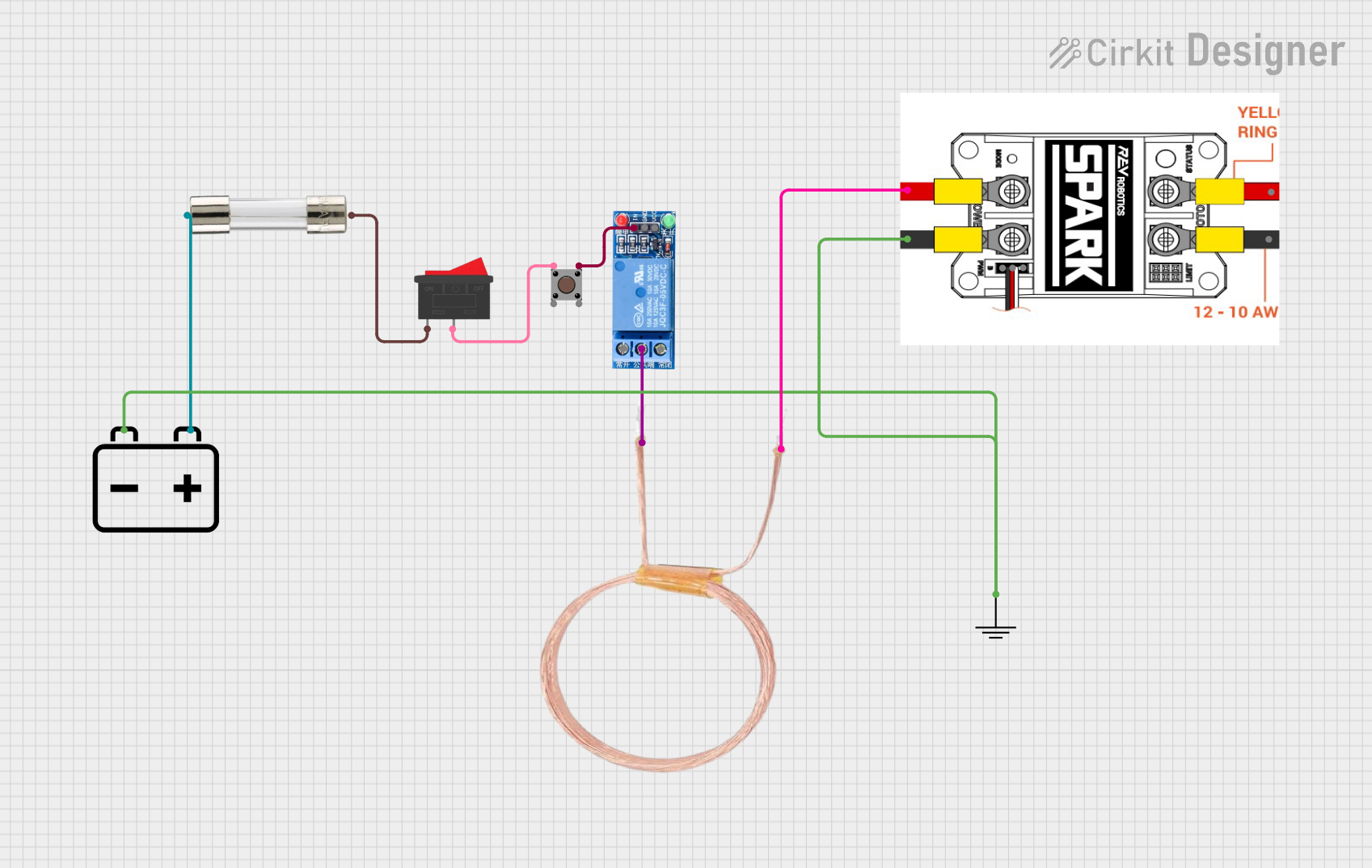
Explore Projects Built with Mini Pushbutton Power Switch with Reverse Voltage Protection, SV
Common Applications
- Battery-powered devices requiring a compact on/off switch
- Robotics and automation systems
- DIY electronics and prototyping
- Low-power circuits needing reverse voltage protection
Technical Specifications
The following table outlines the key technical details of the Mini Pushbutton Power Switch:
| Parameter | Value |
|---|---|
| Operating Voltage Range | 4.5 V to 40 V |
| Maximum Continuous Current | 6 A |
| Reverse Voltage Protection | Yes |
| Control Input Voltage | Logic-level compatible (3.3 V or 5 V logic) |
| Dimensions | 0.6" × 0.8" × 0.1" (15 mm × 20 mm × 3 mm) |
| Weight | 0.6 g |
Pin Configuration and Descriptions
The Mini Pushbutton Power Switch has six pins, as described in the table below:
| Pin Name | Description |
|---|---|
| VIN | Power input pin (connect to the positive terminal of the power source). |
| VOUT | Power output pin (connect to the positive terminal of the load). |
| GND | Ground pin (connect to the negative terminal of the power source and load). |
| ON | Control pin for turning the switch on (active high, logic-level compatible). |
| OFF | Control pin for turning the switch off (active high, logic-level compatible). |
| PUSHBUTTON | Connection point for an external pushbutton to toggle the switch state. |
Usage Instructions
How to Use the Component in a Circuit
Power Connections:
- Connect the positive terminal of your power source to the VIN pin.
- Connect the negative terminal of your power source to the GND pin.
- Connect the positive terminal of your load to the VOUT pin.
- Ensure the negative terminal of your load is also connected to GND.
Control Options:
- To toggle the switch state, connect a momentary pushbutton between the PUSHBUTTON pin and GND.
- Alternatively, use the ON and OFF pins for direct control via a microcontroller or logic circuit.
- Drive the ON pin high to turn the switch on.
- Drive the OFF pin high to turn the switch off.
Reverse Voltage Protection:
- The built-in reverse voltage protection ensures that the circuit remains safe even if the power supply is connected backward. No additional components are required for this protection.
Important Considerations and Best Practices
- Current Limitations: Ensure that the load does not exceed the maximum continuous current rating of 6 A. Exceeding this limit may damage the switch.
- Voltage Range: Operate the switch within the specified voltage range (4.5 V to 40 V) to avoid malfunction or damage.
- Pushbutton Debouncing: If using an external pushbutton, consider adding a debounce circuit or software debounce logic to prevent unintended toggling due to mechanical noise.
- Microcontroller Integration: When connecting to a microcontroller (e.g., Arduino UNO), use logic-level signals (3.3 V or 5 V) for the ON and OFF pins.
Example Arduino Code
Below is an example of how to control the Mini Pushbutton Power Switch using an Arduino UNO:
// Define pin connections for the ON and OFF control pins
const int onPin = 7;  // Connect Arduino pin 7 to the ON pin of the switch
const int offPin = 8; // Connect Arduino pin 8 to the OFF pin of the switch

void setup() {
  // Set the ON and OFF pins as outputs
  pinMode(onPin, OUTPUT);
  pinMode(offPin, OUTPUT);

  // Initially turn the switch off
  digitalWrite(onPin, LOW);
  digitalWrite(offPin, HIGH);
  delay(100); // Small delay to ensure the switch turns off
  digitalWrite(offPin, LOW);
}

void loop() {
  // Example: Turn the switch on for 5 seconds, then off for 5 seconds
  digitalWrite(onPin, HIGH); // Turn the switch on
  delay(100);                // Small delay to ensure the switch turns on
  digitalWrite(onPin, LOW);  // Reset the ON pin
  delay(5000);               // Keep the switch on for 5 seconds

  digitalWrite(offPin, HIGH); // Turn the switch off
  delay(100);                 // Small delay to ensure the switch turns off
  digitalWrite(offPin, LOW);  // Reset the OFF pin
  delay(5000);                // Keep the switch off for 5 seconds
}
Troubleshooting and FAQs
Common Issues and Solutions
Switch Does Not Turn On:
- Verify that the power supply voltage is within the operating range (4.5 V to 40 V).
- Check the connections to the VIN, VOUT, and GND pins.
- Ensure the ON pin or PUSHBUTTON pin is being driven high correctly.
Switch Turns Off Unexpectedly:
- Ensure the load current does not exceed the 6 A maximum rating.
- Check for loose or intermittent connections in the circuit.
Pushbutton Does Not Work:
- Verify that the pushbutton is properly connected between the PUSHBUTTON pin and GND.
- Add a debounce circuit or software debounce logic if the pushbutton toggles the switch state erratically.
Reverse Voltage Protection Not Working:
- Ensure the power supply is connected to the correct pins (VIN and GND).
- Note that the reverse voltage protection only prevents damage; it does not allow the circuit to operate with reversed polarity.
FAQs
Q: Can I use this switch with a 3.3 V power supply?
A: No, the minimum operating voltage is 4.5 V. Using a 3.3 V power supply will not activate the switch.
Q: Is the switch latching or momentary?
A: The switch is latching, meaning it maintains its state (on or off) until toggled again.
Q: Can I control the switch with a microcontroller?
A: Yes, the ON and OFF pins are logic-level compatible and can be controlled with a microcontroller like an Arduino.
Q: Does the switch consume power when off?
A: The switch has a very low quiescent current when off, making it suitable for battery-powered applications.