Cirkit Designer Logo
Cirkit Designer
Your all-in-one circuit design IDE
Home / 
Component Documentation

How to Use DS1302: Examples, Pinouts, and Specs

Image of DS1302
Cirkit Designer LogoDesign with DS1302 in Cirkit Designer

Introduction

The DS1302 is a Real-Time Clock (RTC) integrated circuit that provides precise timekeeping and calendar functionality. It tracks time in seconds, minutes, hours, as well as day, month, and year information. The DS1302 is designed to operate on very low power and retain data and time information on less than 1µW of power, making it ideal for battery-backed non-volatile timekeeping applications.

Common applications of the DS1302 include:

  • Digital clocks and watches
  • Data loggers
  • Timers
  • Embedded systems requiring time-stamped events

Explore Projects Built with DS1302

Use Cirkit Designer to design, explore, and prototype these projects online. Some projects support real-time simulation. Click "Open Project" to start designing instantly!
Arduino UNO Based Touch-Controlled Bluetooth Time Display
Image of smart diary: A project utilizing DS1302 in a practical application
This circuit features an Arduino UNO microcontroller connected to a DS1302 Real Time Clock (RTC) module, a touch sensor, an HC-05 Bluetooth module, and an I2C LCD 16x2 display. The Arduino facilitates communication between the Bluetooth module and the touch sensor, maintains time using the RTC, and outputs information to the LCD display. The provided code skeleton suggests that the Arduino is programmed to perform tasks in a loop, but specific functionality is not detailed in the code.
Cirkit Designer LogoOpen Project in Cirkit Designer
Arduino UNO Real-Time Clock with DS1307 RTC Module
Image of rrtc: A project utilizing DS1302 in a practical application
This circuit interfaces an Arduino UNO with a DS1307 Real-Time Clock (RTC) module. The Arduino communicates with the RTC module using the I2C protocol, with connections from A4 to SDA and A5 to SCL.
Cirkit Designer LogoOpen Project in Cirkit Designer
ESP8266 NodeMCU Based Water Quality Monitoring System with Solar Charging
Image of SISTEMA DE ALIMENTACION Y CARGA PARA EL PROYECTO HUMEDALES CONSTRUIDO UT MATAMOROS: A project utilizing DS1302 in a practical application
This circuit features an ESP8266 NodeMCU microcontroller interfaced with a DS18B20 temperature sensor and a turbidity module to monitor water quality. The NodeMCU reads temperature data from the DS18B20 sensor and turbidity levels from the turbidity module's analog output. Power management is handled by a 18650 Li-ion battery connected to a solar panel and a Do solara charge controller, with voltage regulation provided by an XL6009 module to ensure stable operation of the microcontroller and sensors.
Cirkit Designer LogoOpen Project in Cirkit Designer
Solar-Powered ESP32C3 Environmental Monitoring Station with Actuation
Image of Automatic Fish Feeder: A project utilizing DS1302 in a practical application
This circuit appears to be a microcontroller-based system with environmental sensing and timekeeping capabilities. It uses an ESP32C3 microcontroller to interface with a DS18B20 temperature sensor and a DS1307 real-time clock for temperature data logging and time-stamping. Additionally, the circuit includes a servo motor controlled by the ESP32C3, a solar panel with a charging circuit for a 3.7V battery, and a step-up converter to provide a stable voltage supply.
Cirkit Designer LogoOpen Project in Cirkit Designer

Explore Projects Built with DS1302

Use Cirkit Designer to design, explore, and prototype these projects online. Some projects support real-time simulation. Click "Open Project" to start designing instantly!
Image of smart diary: A project utilizing DS1302 in a practical application
Arduino UNO Based Touch-Controlled Bluetooth Time Display
This circuit features an Arduino UNO microcontroller connected to a DS1302 Real Time Clock (RTC) module, a touch sensor, an HC-05 Bluetooth module, and an I2C LCD 16x2 display. The Arduino facilitates communication between the Bluetooth module and the touch sensor, maintains time using the RTC, and outputs information to the LCD display. The provided code skeleton suggests that the Arduino is programmed to perform tasks in a loop, but specific functionality is not detailed in the code.
Cirkit Designer LogoOpen Project in Cirkit Designer
Image of rrtc: A project utilizing DS1302 in a practical application
Arduino UNO Real-Time Clock with DS1307 RTC Module
This circuit interfaces an Arduino UNO with a DS1307 Real-Time Clock (RTC) module. The Arduino communicates with the RTC module using the I2C protocol, with connections from A4 to SDA and A5 to SCL.
Cirkit Designer LogoOpen Project in Cirkit Designer
Image of SISTEMA DE ALIMENTACION Y CARGA PARA EL PROYECTO HUMEDALES CONSTRUIDO UT MATAMOROS: A project utilizing DS1302 in a practical application
ESP8266 NodeMCU Based Water Quality Monitoring System with Solar Charging
This circuit features an ESP8266 NodeMCU microcontroller interfaced with a DS18B20 temperature sensor and a turbidity module to monitor water quality. The NodeMCU reads temperature data from the DS18B20 sensor and turbidity levels from the turbidity module's analog output. Power management is handled by a 18650 Li-ion battery connected to a solar panel and a Do solara charge controller, with voltage regulation provided by an XL6009 module to ensure stable operation of the microcontroller and sensors.
Cirkit Designer LogoOpen Project in Cirkit Designer
Image of Automatic Fish Feeder: A project utilizing DS1302 in a practical application
Solar-Powered ESP32C3 Environmental Monitoring Station with Actuation
This circuit appears to be a microcontroller-based system with environmental sensing and timekeeping capabilities. It uses an ESP32C3 microcontroller to interface with a DS18B20 temperature sensor and a DS1307 real-time clock for temperature data logging and time-stamping. Additionally, the circuit includes a servo motor controlled by the ESP32C3, a solar panel with a charging circuit for a 3.7V battery, and a step-up converter to provide a stable voltage supply.
Cirkit Designer LogoOpen Project in Cirkit Designer

Technical Specifications

Key Technical Details

  • Voltage Supply: 2.0V to 5.5V
  • Operating Current: 300nA (typical) at 2.0V
  • Timekeeping Current: <1µA (typical)
  • Interface Type: Simple 3-wire interface
  • Frequency Output: 32.768kHz
  • Temperature Range: 0°C to +70°C
  • Data Retention Voltage: Minimum 1.2V

Pin Configuration and Descriptions

Pin Number Name Description
1 X1 Input for the 32.768kHz crystal oscillator
2 X2 Output for the 32.768kHz crystal oscillator
3 GND Ground pin
4 Vcc Power supply pin (2.0V to 5.5V)
5 SCLK Serial clock input for communication
6 I/O Data input/output for communication
7 CE Chip enable, active high
8 Vbat Backup battery input for data retention

Usage Instructions

Interfacing with a Circuit

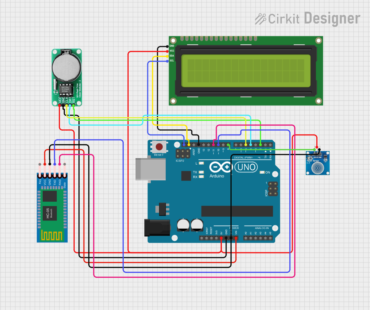
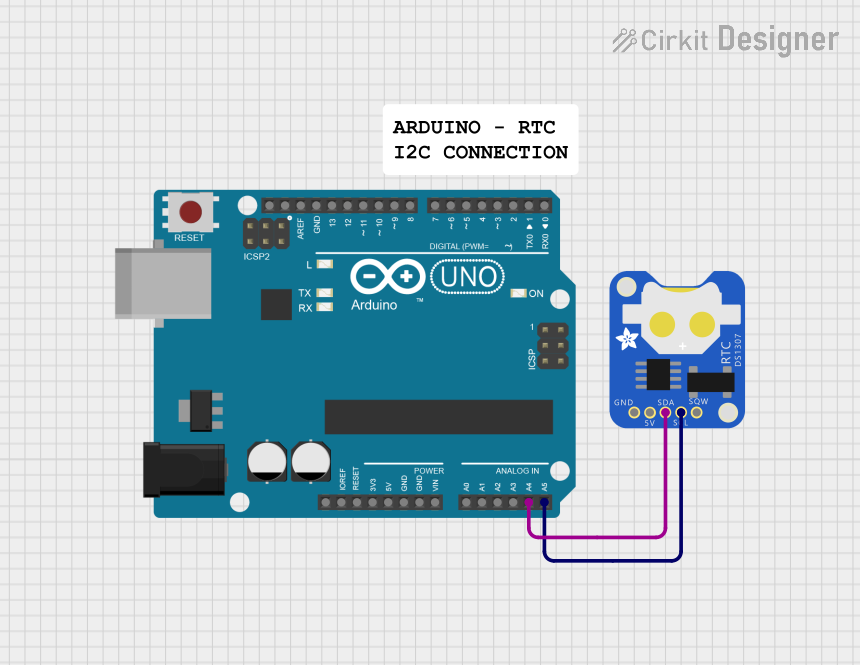
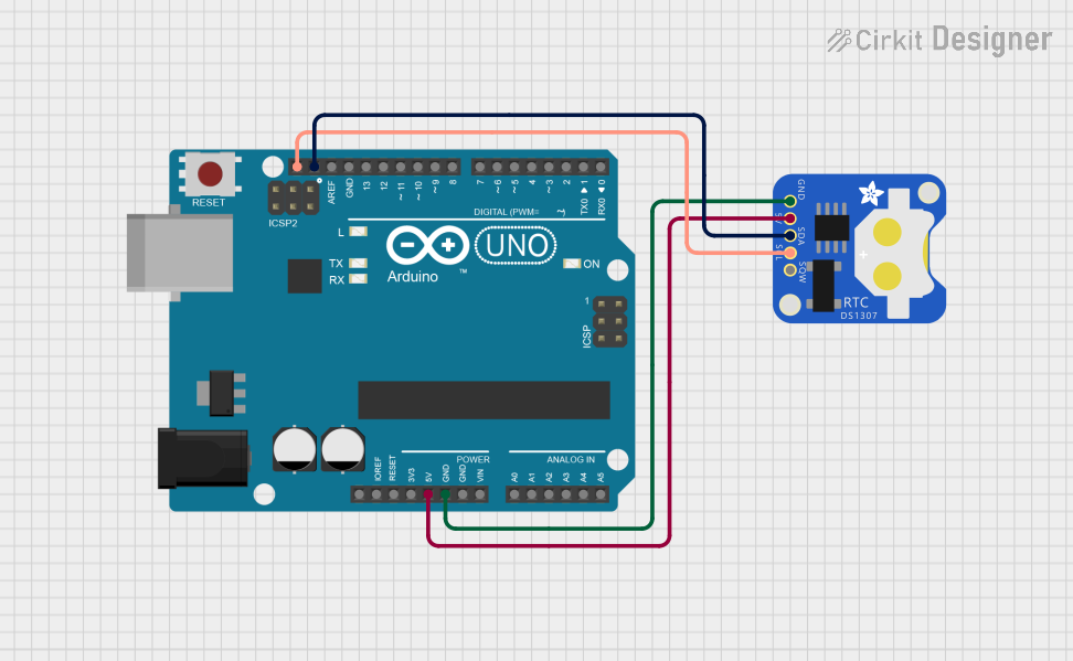
To use the DS1302 in a circuit, connect the Vcc pin to a power supply within the specified range and GND to the system ground. The X1 and X2 pins should be connected to a 32.768kHz crystal. The CE, I/O, and SCLK pins are used for communication with a microcontroller, such as an Arduino UNO.

Best Practices

  • Use a clean, noise-free power supply to minimize timekeeping errors.
  • Place a 0.1µF bypass capacitor close to the Vcc pin to filter out power supply noise.
  • Keep the crystal and DS1302 as close as possible to reduce the effects of noise on the crystal pins.
  • Avoid running high-speed switching lines near the crystal or DS1302 to prevent interference.

Example Code for Arduino UNO

#include <DS1302.h>

// Initialize the DS1302
// CE pin -> Arduino Digital 2
// I/O pin -> Arduino Digital 3
// SCLK pin -> Arduino Digital 4
DS1302 rtc(2, 3, 4);

void setup() {
  Serial.begin(9600);
  rtc.halt(false);  // Enable the clock
  rtc.writeProtect(false);  // Disable write protection

  // Set the time to January 1, 2023, 12:00:00
  rtc.setDOW(SUNDAY);        // Set Day-of-Week to SUNDAY
  rtc.setTime(12, 0, 0);     // Set the time to 12:00:00 (24hr format)
  rtc.setDate(1, 1, 2023);   // Set the date to January 1, 2023
}

void loop() {
  // Print the current date and time to the Serial Monitor
  Serial.print(rtc.getDOWStr());
  Serial.print(" ");
  Serial.print(rtc.getDateStr());
  Serial.print(" -- ");
  Serial.println(rtc.getTimeStr());

  // Wait one second before repeating
  delay(1000);
}

Troubleshooting and FAQs

Common Issues

  • Time not accurate: Ensure the crystal is properly connected and not damaged. Check for noise in the power supply and around the crystal.
  • Cannot communicate with DS1302: Verify the wiring, especially the CE, I/O, and SCLK connections. Ensure the microcontroller pins are configured correctly.
  • Data lost on power failure: Make sure the Vbat pin is connected to a battery that can provide the minimum data retention voltage.

Solutions and Tips

  • If the time drifts significantly, consider using a temperature-compensated crystal oscillator (TCXO).
  • For communication issues, use an oscilloscope to check the signal integrity of the SCLK, CE, and I/O lines.
  • Always check the battery voltage connected to Vbat to ensure it's above the data retention threshold.

FAQs

Q: Can the DS1302 be used in a 5V system? A: Yes, the DS1302 can operate in systems with a supply voltage from 2.0V to 5.5V.

Q: How long will the DS1302 keep time on a battery backup? A: This depends on the battery capacity and the quality of the crystal. With a good quality coin cell and crystal, the DS1302 can keep time for several years.

Q: Is the DS1302 Y2K compliant? A: Yes, the DS1302 has a century bit that allows it to be used well beyond the year 2000.

Q: Does the DS1302 account for leap years? A: Yes, the DS1302 automatically adjusts for months with fewer than 31 days, including corrections for leap year.

For further assistance, consult the DS1302 datasheet or contact technical support.