How to Use PCF8574: Examples, Pinouts, and Specs
Introduction
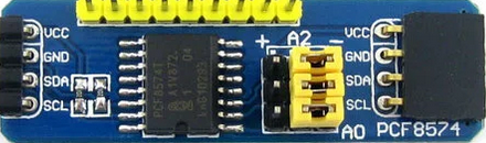
The PCF8574, manufactured by Texas Instruments, is an I2C I/O expander that provides 8 additional digital input/output pins to a microcontroller. This component is particularly useful in applications where the number of GPIO pins on a microcontroller is insufficient. By utilizing the I2C communication protocol, the PCF8574 allows for efficient control of multiple devices with minimal pin usage.
Explore Projects Built with PCF8574


Explore Projects Built with PCF8574
Common Applications and Use Cases
- Expanding GPIO pins for microcontrollers like Arduino, Raspberry Pi, or ESP32.
- Driving LEDs, relays, or other digital devices.
- Reading the state of switches, buttons, or sensors.
- Building keypad interfaces or matrix displays.
- Applications requiring multiple I/O operations with limited microcontroller pins.
Technical Specifications
The following are the key technical details of the PCF8574:
| Parameter | Value |
|---|---|
| Operating Voltage (Vcc) | 2.5V to 6V |
| I2C Bus Speed | Up to 100 kHz (Standard Mode) |
| Number of I/O Pins | 8 (configurable as input or output) |
| Maximum Sink Current (per pin) | 25 mA |
| Maximum Source Current (per pin) | -300 µA |
| I2C Address Range | 0x20 to 0x27 (configurable via address pins) |
| Operating Temperature Range | -40°C to 85°C |
| Package Types | SOIC, PDIP, TSSOP |
Pin Configuration and Descriptions
The PCF8574 has 16 pins, with the following configuration:
| Pin Number | Pin Name | Description |
|---|---|---|
| 1 | A0 | I2C Address Selection Bit 0 |
| 2 | A1 | I2C Address Selection Bit 1 |
| 3 | A2 | I2C Address Selection Bit 2 |
| 4 | P0 | General Purpose I/O Pin 0 |
| 5 | P1 | General Purpose I/O Pin 1 |
| 6 | P2 | General Purpose I/O Pin 2 |
| 7 | P3 | General Purpose I/O Pin 3 |
| 8 | GND | Ground |
| 9 | P4 | General Purpose I/O Pin 4 |
| 10 | P5 | General Purpose I/O Pin 5 |
| 11 | P6 | General Purpose I/O Pin 6 |
| 12 | P7 | General Purpose I/O Pin 7 |
| 13 | INT | Interrupt Output (active LOW) |
| 14 | SCL | I2C Clock Line |
| 15 | SDA | I2C Data Line |
| 16 | VCC | Power Supply (2.5V to 6V) |
Usage Instructions
How to Use the PCF8574 in a Circuit
- Power Supply: Connect the VCC pin to a 2.5V–6V power source and the GND pin to ground.
- I2C Address Configuration: Use the A0, A1, and A2 pins to set the I2C address. These pins can be connected to VCC (logic HIGH) or GND (logic LOW) to configure the address. The base address is
0x20, and the address range is0x20to0x27. - I2C Communication: Connect the SDA and SCL pins to the corresponding I2C pins on the microcontroller. Use pull-up resistors (typically 4.7kΩ) on the SDA and SCL lines if not already present.
- I/O Configuration: The 8 GPIO pins (P0–P7) can be configured as inputs or outputs. When configured as inputs, external pull-up resistors may be required.
- Interrupt Pin (Optional): The INT pin can be used to detect changes on input pins. It is active LOW and requires an external pull-up resistor.
Example: Connecting the PCF8574 to an Arduino UNO
Below is an example of how to use the PCF8574 with an Arduino UNO to control LEDs:
Circuit Connections
- Connect the PCF8574's SDA and SCL pins to the Arduino's A4 (SDA) and A5 (SCL) pins, respectively.
- Connect the VCC and GND pins of the PCF8574 to the Arduino's 5V and GND pins.
- Connect LEDs to the P0–P3 pins of the PCF8574, with appropriate current-limiting resistors.
Arduino Code
#include <Wire.h> // Include the Wire library for I2C communication

#define PCF8574_ADDRESS 0x20 // I2C address of the PCF8574 (default: 0x20)

void setup() {
  Wire.begin(); // Initialize I2C communication
  Serial.begin(9600); // Initialize serial communication for debugging

  // Set all pins (P0–P7) as outputs by writing HIGH to all pins
  Wire.beginTransmission(PCF8574_ADDRESS);
  Wire.write(0xFF); // All pins HIGH (default state for outputs)
  Wire.endTransmission();
}

void loop() {
  // Example: Blink an LED connected to P0
  Wire.beginTransmission(PCF8574_ADDRESS);
  Wire.write(0xFE); // Set P0 LOW, others HIGH
  Wire.endTransmission();
  delay(500); // Wait for 500ms

  Wire.beginTransmission(PCF8574_ADDRESS);
  Wire.write(0xFF); // Set all pins HIGH
  Wire.endTransmission();
  delay(500); // Wait for 500ms
}
Important Considerations and Best Practices
- Pull-Up Resistors: Ensure proper pull-up resistors are used on the SDA and SCL lines for reliable I2C communication.
- Current Limitations: The PCF8574 can sink up to 25 mA per pin but can only source a small current (-300 µA). Use external transistors or drivers for higher current requirements.
- Interrupt Handling: If using the INT pin, ensure it is connected to a microcontroller pin capable of handling interrupts.
Troubleshooting and FAQs
Common Issues and Solutions
I2C Communication Failure
- Cause: Incorrect I2C address or missing pull-up resistors.
- Solution: Verify the I2C address configuration (A0, A1, A2 pins) and ensure pull-up resistors (4.7kΩ) are connected to the SDA and SCL lines.
GPIO Pins Not Responding
- Cause: Incorrect configuration of pins as input or output.
- Solution: Double-check the data written to the PCF8574 to ensure the desired pin states are set.
Interrupt Pin Not Working
- Cause: INT pin not connected or improperly configured.
- Solution: Connect the INT pin to a microcontroller interrupt-capable pin and ensure it is pulled HIGH with a resistor.
LEDs Not Lighting Up
- Cause: Exceeding the current sourcing capability of the PCF8574.
- Solution: Use external transistors or drivers to handle higher current loads.
FAQs
Can the PCF8574 handle analog signals?
- No, the PCF8574 is designed for digital input/output only.
What is the maximum number of PCF8574 devices that can be connected to a single I2C bus?
- Up to 8 devices can be connected, as the PCF8574 supports 3 address pins (A0, A1, A2), allowing for 8 unique addresses.
Can the PCF8574 be used with 3.3V microcontrollers?
- Yes, the PCF8574 operates with a supply voltage range of 2.5V to 6V, making it compatible with 3.3V systems.
How do I configure a pin as an input?
- To configure a pin as an input, write a HIGH state to the corresponding bit. The pin will then act as an input with a weak pull-up.
By following this documentation, users can effectively integrate the PCF8574 into their projects and expand the GPIO capabilities of their microcontrollers.