How to Use DC Motor Encoder: Examples, Pinouts, and Specs
Introduction
A DC Motor Encoder is a device that provides feedback on the position, speed, and direction of a DC motor's rotation. It typically uses optical or magnetic sensors to convert the rotational movement into electrical signals. This feedback enables precise control of the motor, making it an essential component in applications such as robotics, automation, CNC machines, and other systems requiring accurate motor control.
Common applications and use cases:
- Robotics for precise movement and positioning
- Conveyor belt systems for speed and direction control
- CNC machines for accurate cutting and shaping
- Automated guided vehicles (AGVs) for navigation
- Industrial automation for process control
Explore Projects Built with DC Motor Encoder

Explore Projects Built with DC Motor Encoder
Technical Specifications
Below are the typical technical specifications for a DC Motor Encoder. Note that actual values may vary depending on the specific model.
| Parameter | Specification |
|---|---|
| Operating Voltage | 3.3V to 5V |
| Output Signal Type | Quadrature (A and B channels) |
| Resolution | 100 to 2000 pulses per revolution (PPR) |
| Maximum RPM | 6000 RPM |
| Output Signal Voltage | TTL compatible (0V to 5V) |
| Operating Temperature | -20°C to 85°C |
| Sensor Type | Optical or Magnetic |
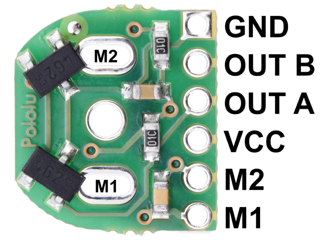
Pin Configuration and Descriptions
The pinout of a typical DC Motor Encoder is as follows:
| Pin | Name | Description |
|---|---|---|
| 1 | VCC | Power supply input (3.3V to 5V) |
| 2 | GND | Ground connection |
| 3 | A (Channel A) | Quadrature signal output for position/speed feedback |
| 4 | B (Channel B) | Quadrature signal output for position/speed feedback |
| 5 | Index (Optional) | Optional index pulse for absolute position reference |
Usage Instructions
How to Use the Component in a Circuit
- Power the Encoder: Connect the VCC pin to a 3.3V or 5V power source and the GND pin to the ground of your circuit.
- Connect Signal Pins: Connect the A and B output pins to the microcontroller or motor driver. These pins provide the quadrature signals for position and speed feedback.
- Optional Index Pin: If your encoder has an index pin, connect it to the microcontroller for absolute position reference (if required).
- Read the Signals: Use a microcontroller (e.g., Arduino UNO) to read the A and B signals. These signals can be used to determine the motor's speed, direction, and position.
Important Considerations and Best Practices
- Debouncing: Use hardware or software debouncing to filter out noise in the encoder signals.
- Pull-up Resistors: Some encoders may require external pull-up resistors on the A and B signal lines.
- Alignment: Ensure proper alignment of the encoder with the motor shaft to avoid signal errors.
- RPM Limit: Verify that the encoder's maximum RPM rating is not exceeded during operation.
- Shielding: Use shielded cables for the encoder signals to minimize interference in noisy environments.
Example Code for Arduino UNO
Below is an example of how to interface a DC Motor Encoder with an Arduino UNO to read position and direction.
// Example code to read a DC Motor Encoder with Arduino UNO
// Connect encoder pins: A -> Pin 2, B -> Pin 3

volatile int position = 0; // Variable to store encoder position
int lastDirection = 0;     // Variable to store last direction (1 = CW, -1 = CCW)

// Interrupt service routine for Channel A
void ISR_A() {
  // Read Channel B to determine direction
  if (digitalRead(3) == HIGH) {
    position++; // Clockwise rotation
    lastDirection = 1;
  } else {
    position--; // Counterclockwise rotation
    lastDirection = -1;
  }
}

void setup() {
  pinMode(2, INPUT_PULLUP); // Set Channel A as input with pull-up
  pinMode(3, INPUT_PULLUP); // Set Channel B as input with pull-up

  attachInterrupt(digitalPinToInterrupt(2), ISR_A, CHANGE); // Attach interrupt to Channel A

  Serial.begin(9600); // Initialize serial communication
}

void loop() {
  // Print position and direction to the Serial Monitor
  Serial.print("Position: ");
  Serial.print(position);
  Serial.print(" | Direction: ");
  if (lastDirection == 1) {
    Serial.println("Clockwise");
  } else if (lastDirection == -1) {
    Serial.println("Counterclockwise");
  } else {
    Serial.println("Unknown");
  }

  delay(100); // Delay for readability
}
Troubleshooting and FAQs
Common Issues and Solutions
No Signal Output:
- Cause: Incorrect wiring or insufficient power supply.
- Solution: Double-check the connections and ensure the encoder is powered with the correct voltage.
Erratic or Noisy Signals:
- Cause: Electrical noise or misalignment of the encoder.
- Solution: Use shielded cables, add capacitors for noise filtering, and ensure proper alignment.
Incorrect Direction Detection:
- Cause: Swapped A and B signal connections.
- Solution: Swap the connections of the A and B pins to the microcontroller.
Position Drift:
- Cause: Missing pulses due to high RPM or poor signal quality.
- Solution: Ensure the encoder's RPM rating is not exceeded and use a microcontroller with fast interrupt handling.
FAQs
Q: Can I use a DC Motor Encoder with a 12V power supply?
A: No, most encoders operate at 3.3V to 5V. Using a 12V supply may damage the encoder. Use a voltage regulator if needed.
Q: How do I calculate the motor's speed using the encoder?
A: Count the number of pulses in a fixed time interval and multiply by the encoder's resolution (PPR) to calculate the speed in RPM.
Q: Can I use the encoder for absolute positioning?
A: Standard encoders provide relative positioning. However, if the encoder has an index pulse, it can be used for absolute positioning when combined with a reference point.
Q: What is the difference between optical and magnetic encoders?
A: Optical encoders use light sensors for signal generation, while magnetic encoders use magnetic fields. Optical encoders are more precise, but magnetic encoders are more robust in harsh environments.