Cirkit Designer Logo
Cirkit Designer
Your all-in-one circuit design IDE
Home / 
Component Documentation

How to Use AMS1117 5V-3.3V Step Down: Examples, Pinouts, and Specs

Image of AMS1117 5V-3.3V Step Down
Cirkit Designer LogoDesign with AMS1117 5V-3.3V Step Down in Cirkit Designer

Introduction

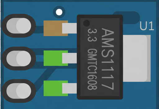
The AMS1117 5V-3.3V Step Down is a low-dropout (LDO) voltage regulator designed to convert a 5V input into a stable 3.3V output. This component is widely used in electronic circuits to power low-voltage devices such as microcontrollers, sensors, and communication modules. Its compact design and reliable performance make it a popular choice for both hobbyists and professionals.

Explore Projects Built with AMS1117 5V-3.3V Step Down

Use Cirkit Designer to design, explore, and prototype these projects online. Some projects support real-time simulation. Click "Open Project" to start designing instantly!
Battery-Powered Arduino UNO and ESP-8266 Smart Controller with LCD and RTC
Image of Ogie Diagram: A project utilizing AMS1117 5V-3.3V Step Down in a practical application
This circuit is a power management and control system that uses a 12V power supply and a 18650 Li-ion battery pack to provide a stable 5V output through a step-down buck converter. It includes an Arduino UNO, an ESP-8266 controller, a DS1307 RTC module, and a 20x4 I2C LCD display for monitoring and control purposes. The ULN2003A breakout board is used for driving higher current loads.
Cirkit Designer LogoOpen Project in Cirkit Designer
Battery-Powered 18650 Li-ion Charger with USB Output and Adjustable Voltage Regulator
Image of Breadboard: A project utilizing AMS1117 5V-3.3V Step Down in a practical application
This circuit is a battery management and power supply system that uses three 3.7V batteries connected to a 3S 10A Li-ion 18650 Charger Protection Board Module for balanced charging and protection. The system includes a TP4056 Battery Charging Protection Module for additional charging safety, a Step Up Boost Power Converter to regulate and boost the voltage, and a USB regulator to provide a stable 5V output, controlled by a push switch.
Cirkit Designer LogoOpen Project in Cirkit Designer
ESP32-Powered Wi-Fi Enabled Microcontroller Circuit with AMS1117 Voltage Regulation
Image of Power regualator: A project utilizing AMS1117 5V-3.3V Step Down in a practical application
This circuit features an ESP32 microcontroller powered by a 3.3V AMS1117 voltage regulator. The power is supplied through a 2.1mm DC barrel jack, which provides the input voltage to the AMS1117, and the regulated 3.3V output is connected to the ESP32's VIN pin. The ground connections are shared among the ESP32 and the voltage regulator.
Cirkit Designer LogoOpen Project in Cirkit Designer
ESP32-Based Smart Energy Monitoring and Control System
Image of SMART SOCKET: A project utilizing AMS1117 5V-3.3V Step Down in a practical application
This circuit is designed to monitor AC voltage and current using ZMPT101B and ZMCT103C sensors, respectively, with an ESP32 microcontroller processing the sensor outputs. The XL4015 step-down module regulates the power supply to provide a stable voltage to the sensors, the ESP32, and an LCD I2C display. The ESP32 controls a 4-channel relay module for switching AC loads, and the system's operation can be interacted with via the LCD display and a push switch.
Cirkit Designer LogoOpen Project in Cirkit Designer

Explore Projects Built with AMS1117 5V-3.3V Step Down

Use Cirkit Designer to design, explore, and prototype these projects online. Some projects support real-time simulation. Click "Open Project" to start designing instantly!
Image of Ogie Diagram: A project utilizing AMS1117 5V-3.3V Step Down in a practical application
Battery-Powered Arduino UNO and ESP-8266 Smart Controller with LCD and RTC
This circuit is a power management and control system that uses a 12V power supply and a 18650 Li-ion battery pack to provide a stable 5V output through a step-down buck converter. It includes an Arduino UNO, an ESP-8266 controller, a DS1307 RTC module, and a 20x4 I2C LCD display for monitoring and control purposes. The ULN2003A breakout board is used for driving higher current loads.
Cirkit Designer LogoOpen Project in Cirkit Designer
Image of Breadboard: A project utilizing AMS1117 5V-3.3V Step Down in a practical application
Battery-Powered 18650 Li-ion Charger with USB Output and Adjustable Voltage Regulator
This circuit is a battery management and power supply system that uses three 3.7V batteries connected to a 3S 10A Li-ion 18650 Charger Protection Board Module for balanced charging and protection. The system includes a TP4056 Battery Charging Protection Module for additional charging safety, a Step Up Boost Power Converter to regulate and boost the voltage, and a USB regulator to provide a stable 5V output, controlled by a push switch.
Cirkit Designer LogoOpen Project in Cirkit Designer
Image of Power regualator: A project utilizing AMS1117 5V-3.3V Step Down in a practical application
ESP32-Powered Wi-Fi Enabled Microcontroller Circuit with AMS1117 Voltage Regulation
This circuit features an ESP32 microcontroller powered by a 3.3V AMS1117 voltage regulator. The power is supplied through a 2.1mm DC barrel jack, which provides the input voltage to the AMS1117, and the regulated 3.3V output is connected to the ESP32's VIN pin. The ground connections are shared among the ESP32 and the voltage regulator.
Cirkit Designer LogoOpen Project in Cirkit Designer
Image of SMART SOCKET: A project utilizing AMS1117 5V-3.3V Step Down in a practical application
ESP32-Based Smart Energy Monitoring and Control System
This circuit is designed to monitor AC voltage and current using ZMPT101B and ZMCT103C sensors, respectively, with an ESP32 microcontroller processing the sensor outputs. The XL4015 step-down module regulates the power supply to provide a stable voltage to the sensors, the ESP32, and an LCD I2C display. The ESP32 controls a 4-channel relay module for switching AC loads, and the system's operation can be interacted with via the LCD display and a push switch.
Cirkit Designer LogoOpen Project in Cirkit Designer

Common Applications and Use Cases

  • Powering 3.3V microcontrollers (e.g., ESP8266, ESP32)
  • Supplying stable voltage to sensors and modules
  • Voltage regulation in battery-powered devices
  • Prototyping and breadboard projects

Technical Specifications

The AMS1117 5V-3.3V Step Down regulator is designed for efficient and stable voltage conversion. Below are its key technical details:

Parameter Value
Input Voltage Range 4.5V to 15V
Output Voltage 3.3V
Output Current Up to 1A
Dropout Voltage 1.1V (typical at 1A load)
Quiescent Current 5mA (typical)
Operating Temperature -40°C to +125°C
Package Type SOT-223, TO-252

Pin Configuration and Descriptions

The AMS1117 has three pins, as described in the table below:

Pin Number Pin Name Description
1 GND Ground pin. Connect to the circuit's ground.
2 VOUT Regulated 3.3V output. Connect to the load.
3 VIN Input voltage. Connect to a 5V power source.

Usage Instructions

How to Use the AMS1117 in a Circuit

  1. Connect the Input Voltage (VIN):
    Provide a stable input voltage between 4.5V and 15V to the VIN pin. For a 5V to 3.3V conversion, connect a 5V power source to this pin.

  2. Connect the Ground (GND):
    Connect the GND pin to the ground of your circuit.

  3. Connect the Output Voltage (VOUT):
    The VOUT pin provides a stable 3.3V output. Connect this pin to the device or circuit requiring 3.3V.

  4. Add Decoupling Capacitors:
    To ensure stable operation, place a 10µF capacitor between VIN and GND, and another 10µF capacitor between VOUT and GND. These capacitors help filter noise and improve stability.

Important Considerations and Best Practices

  • Heat Dissipation: The AMS1117 can generate heat during operation, especially at higher input voltages and loads. Use a heatsink or ensure proper ventilation if the regulator gets too hot.
  • Input Voltage Range: Ensure the input voltage is at least 1.1V higher than the output voltage (dropout voltage) for proper regulation.
  • Current Limitations: Do not exceed the maximum output current of 1A to avoid damaging the regulator.
  • PCB Layout: Keep the input and output capacitors as close as possible to the regulator pins to minimize noise and improve performance.

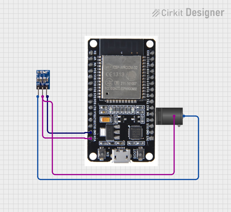
Example: Using AMS1117 with Arduino UNO

The AMS1117 can be used to power 3.3V devices in Arduino projects. Below is an example of connecting the AMS1117 to an ESP8266 module:

Circuit Connections

  • Connect the 5V output from the Arduino UNO to the VIN pin of the AMS1117.
  • Connect the GND pin of the AMS1117 to the Arduino's GND.
  • Connect the VOUT pin of the AMS1117 to the 3.3V input of the ESP8266.

Sample Code for Arduino UNO

// Example code to communicate with an ESP8266 module powered by AMS1117
#include <SoftwareSerial.h>

// Define RX and TX pins for SoftwareSerial
SoftwareSerial esp8266(2, 3); // RX = pin 2, TX = pin 3

void setup() {
  Serial.begin(9600); // Start Serial Monitor at 9600 baud
  esp8266.begin(9600); // Start ESP8266 communication at 9600 baud

  Serial.println("Initializing ESP8266...");
  esp8266.println("AT"); // Send AT command to check communication

  delay(1000); // Wait for response
  while (esp8266.available()) {
    Serial.write(esp8266.read()); // Print ESP8266 response to Serial Monitor
  }
}

void loop() {
  // Add your main code here
}

Troubleshooting and FAQs

Common Issues and Solutions

  1. Output Voltage is Incorrect (Not 3.3V):

    • Cause: Insufficient input voltage or missing decoupling capacitors.
    • Solution: Ensure the input voltage is at least 4.5V and add 10µF capacitors to VIN and VOUT.
  2. Regulator Overheats:

    • Cause: High input voltage or excessive load current.
    • Solution: Use a heatsink or reduce the load current. Ensure the input voltage is within the recommended range.
  3. No Output Voltage:

    • Cause: Incorrect wiring or damaged component.
    • Solution: Double-check the connections and replace the AMS1117 if necessary.
  4. Noise or Instability in Output Voltage:

    • Cause: Missing or improperly placed capacitors.
    • Solution: Place the capacitors as close as possible to the regulator pins.

FAQs

Q: Can I use the AMS1117 to power a 3.3V microcontroller directly?
A: Yes, the AMS1117 is suitable for powering 3.3V microcontrollers, provided the current requirement does not exceed 1A.

Q: What happens if the input voltage drops below 4.5V?
A: The AMS1117 may fail to regulate the output voltage properly, leading to instability or a lower-than-expected output voltage.

Q: Can I use the AMS1117 without capacitors?
A: It is not recommended. Decoupling capacitors are essential for stable operation and noise filtering.

Q: Is the AMS1117 suitable for battery-powered applications?
A: Yes, but ensure the battery voltage remains within the input voltage range of the AMS1117.