How to Use Arcade Button (white): Examples, Pinouts, and Specs
Introduction
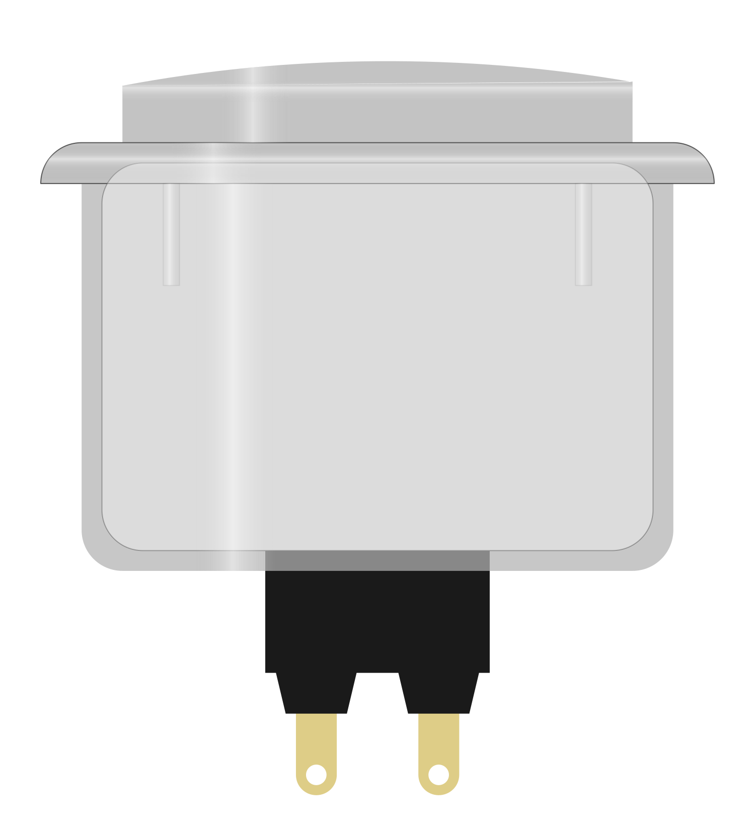
The Arcade Button (White) is a momentary push button designed for high-use applications such as arcade game machines and interactive projects. It features a robust build to withstand frequent presses and provides tactile feedback with a satisfying click. These buttons are popular in DIY electronics due to their ease of use and durability.
Explore Projects Built with Arcade Button (white)
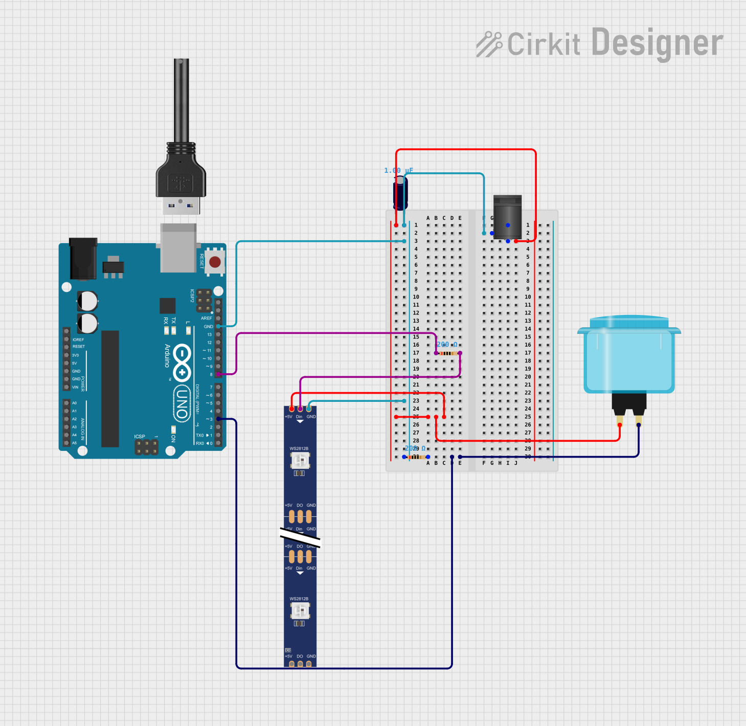
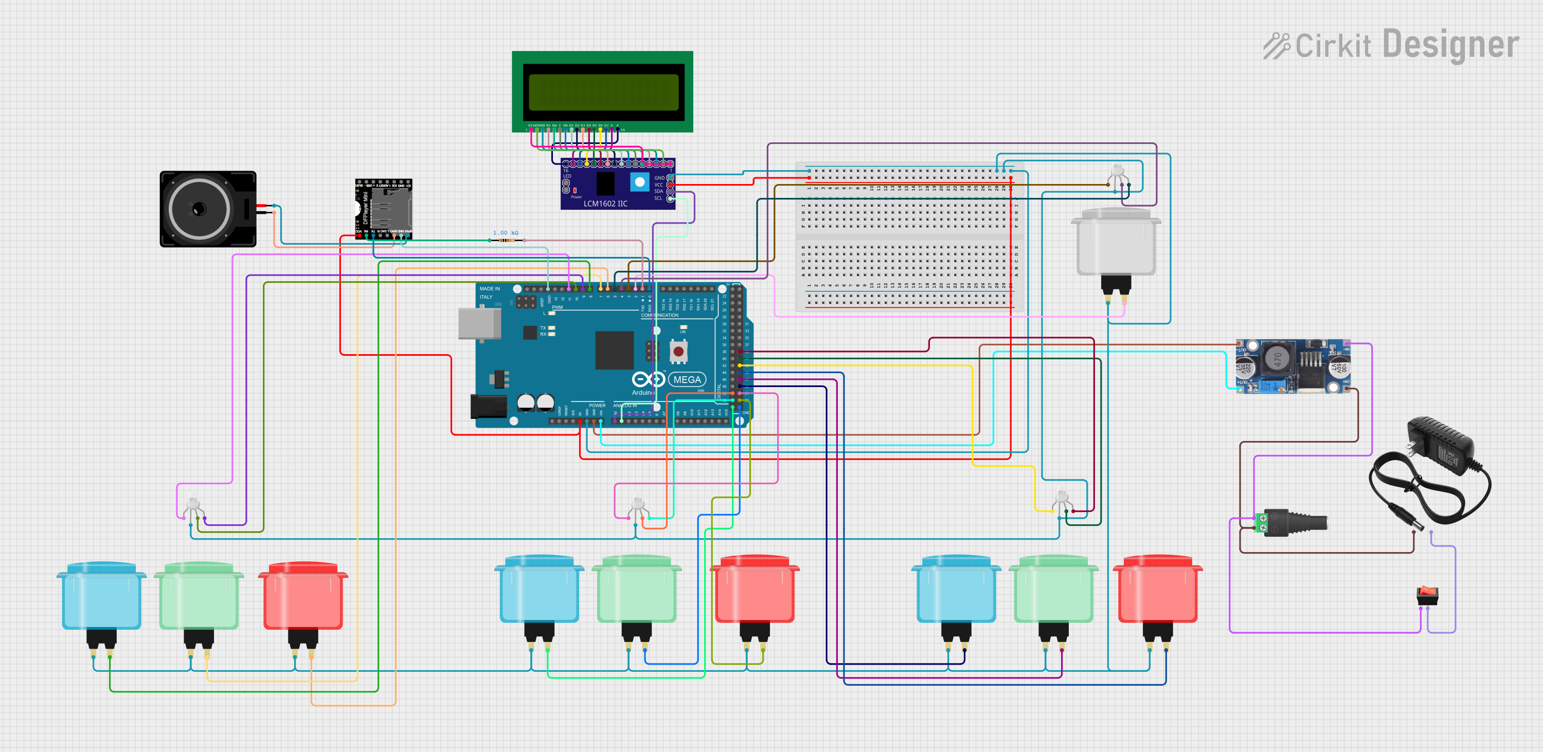
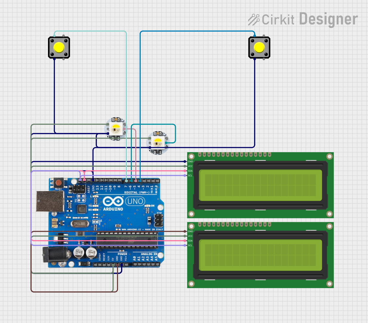
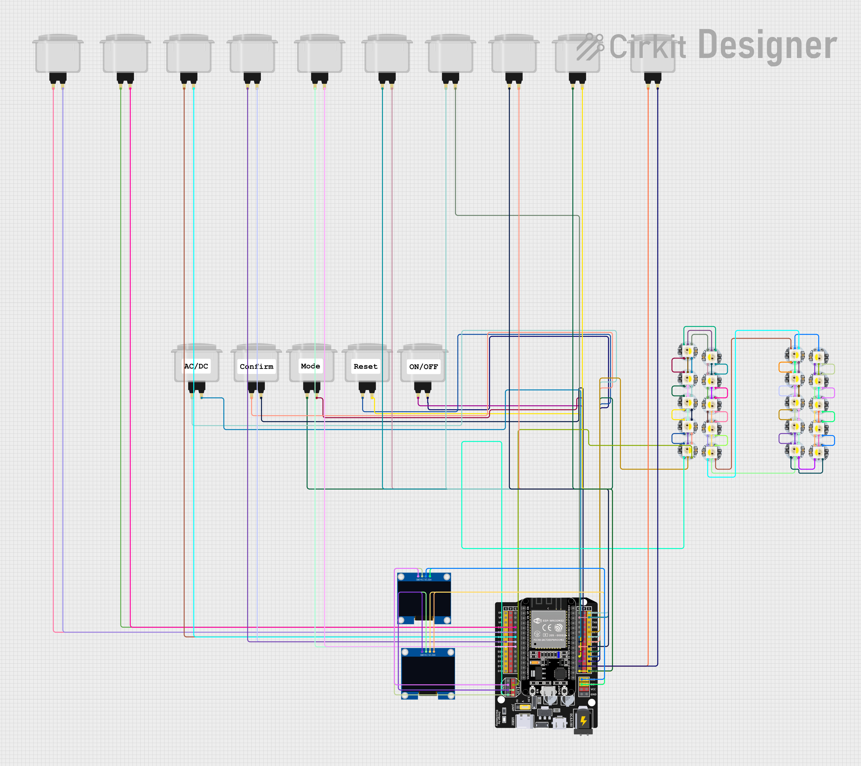
Explore Projects Built with Arcade Button (white)
Common Applications and Use Cases
- Arcade machine controls
- DIY game controllers
- Interactive exhibits
- Educational projects
- Custom keyboards
- Home automation interfaces
Technical Specifications
Key Technical Details
- Switch Type: Momentary contact
- Contact Rating: 3A @ 125V AC or 1.5A @ 250V AC
- Terminal Type: Microswitch with .187" (4.75mm) spade connectors
- Operation Force: Approximately 2.5N to 4.5N
- Travel Distance: About 1.5mm to 2mm actuation, 4mm to 5mm total
- Button Diameter: Typically 30mm to 35mm
- Mounting Hole Size: 28mm to 32mm
- Material: Durable plastic with a microswitch made of metal and plastic components
- Color: White (button cap), often with a black microswitch
Pin Configuration and Descriptions
| Pin Number | Description | Notes |
|---|---|---|
| 1 | Normally Open (NO) | Connects to signal when pressed |
| 2 | Common (COM) | Connects to ground |
| 3 | Normally Closed (NC) | Connected to signal by default |
Usage Instructions
How to Use the Component in a Circuit
- Mounting the Button: Secure the arcade button into a panel with the appropriate hole size. Ensure it is firmly in place.
- Wiring the Button:
- Connect the COM pin to the ground of your circuit.
- Connect the NO pin to the input pin on your microcontroller (e.g., Arduino).
- Optionally, the NC pin can be used if a normally closed configuration is required.
- Debouncing: Implement software debouncing to ensure single actuation per press.
- Testing: Verify the button's operation by checking for continuity with a multimeter when pressed.
Important Considerations and Best Practices
- Current Limitation: Do not exceed the contact rating of the button.
- Debouncing: Always debounce the button either through hardware (e.g., using a capacitor) or software to prevent false triggering.
- Wiring: Use wires that can handle the current and are long enough for your setup.
- Accessibility: Place the button within comfortable reach of the user.
Example Code for Arduino UNO
// Define the pin where the button is connected
const int buttonPin = 2;
// Variable to store the button state
int buttonState = 0;

void setup() {
  // Initialize the button pin as an input
  pinMode(buttonPin, INPUT_PULLUP);
  // Begin serial communication at 9600 baud rate
  Serial.begin(9600);
}

void loop() {
  // Read the state of the button
  buttonState = digitalRead(buttonPin);
  // Check if the button is pressed
  if (buttonState == LOW) {
    // If the button is pressed, print this message
    Serial.println("Button Pressed");
    // Delay to debounce
    delay(50);
  }
}
Troubleshooting and FAQs
Common Issues Users Might Face
- Button does not respond: Ensure the button is correctly wired and the microswitch is not damaged.
- Multiple inputs from a single press: Implement debouncing in your code to resolve this.
- Button sticks when pressed: Check for any obstructions or misalignment in the button assembly.
Solutions and Tips for Troubleshooting
- Check Connections: Verify all connections are secure and correct.
- Test Continuity: Use a multimeter to check the continuity of the button when pressed.
- Replace Microswitch: If the button is unresponsive, consider replacing the microswitch.
FAQs
Q: Can I use the arcade button with a 5V circuit? A: Yes, the arcade button can be used with a 5V circuit, such as an Arduino.
Q: How can I light up the arcade button? A: Some arcade buttons come with built-in LEDs. Connect the LED terminals to a power source with the appropriate resistor.
Q: What is the lifespan of an arcade button? A: Arcade buttons are designed for frequent use and typically have a lifespan of several hundred thousand cycles.