
How to Use ESP32-S3 CAM Development Board with OV3660 Camera Module: Examples, Pinouts, and Specs
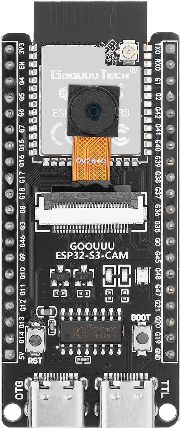
 Design with ESP32-S3 CAM Development Board with OV3660 Camera Module in Cirkit Designer
Introduction
The ESP32-S3 CAM Development Board (Manufacturer Part ID: N16R8) by Espressif is a powerful and versatile development platform designed for IoT applications. It features the ESP32-S3 microcontroller, which integrates Wi-Fi and Bluetooth connectivity, and an OV3660 camera module for high-quality image capture and processing. This board is ideal for projects involving real-time video streaming, image recognition, and edge AI applications.
Explore Projects Built with ESP32-S3 CAM Development Board with OV3660 Camera Module
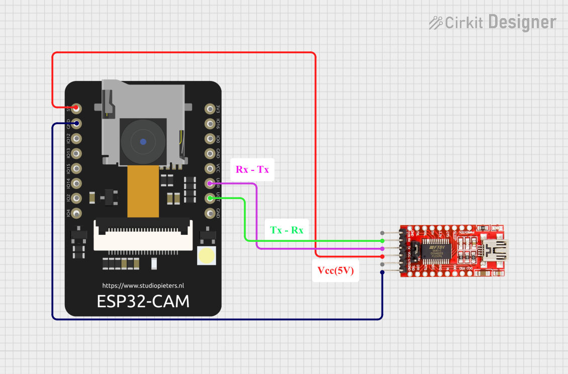 Open Project in Cirkit Designer
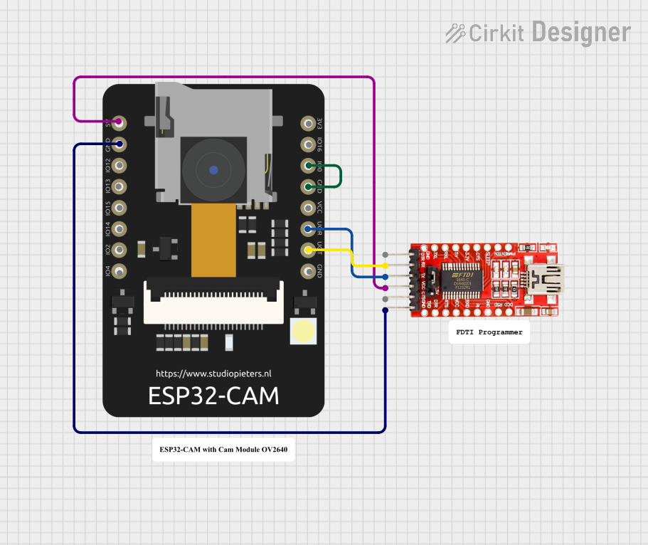 Open Project in Cirkit Designer
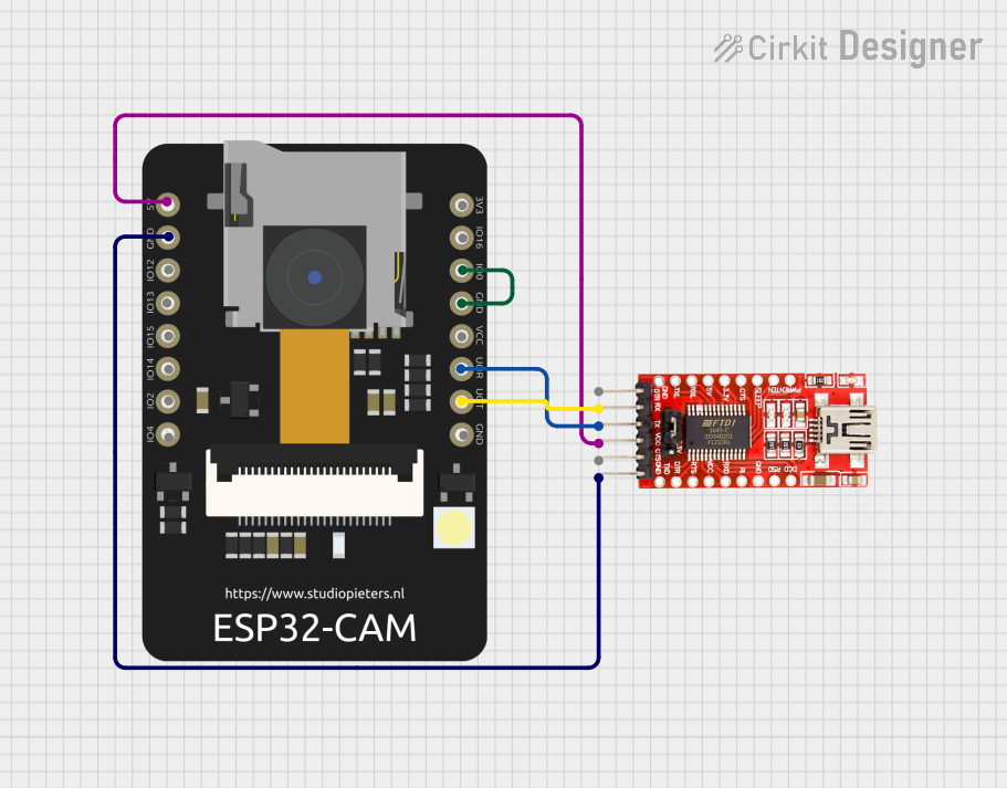 Open Project in Cirkit Designer
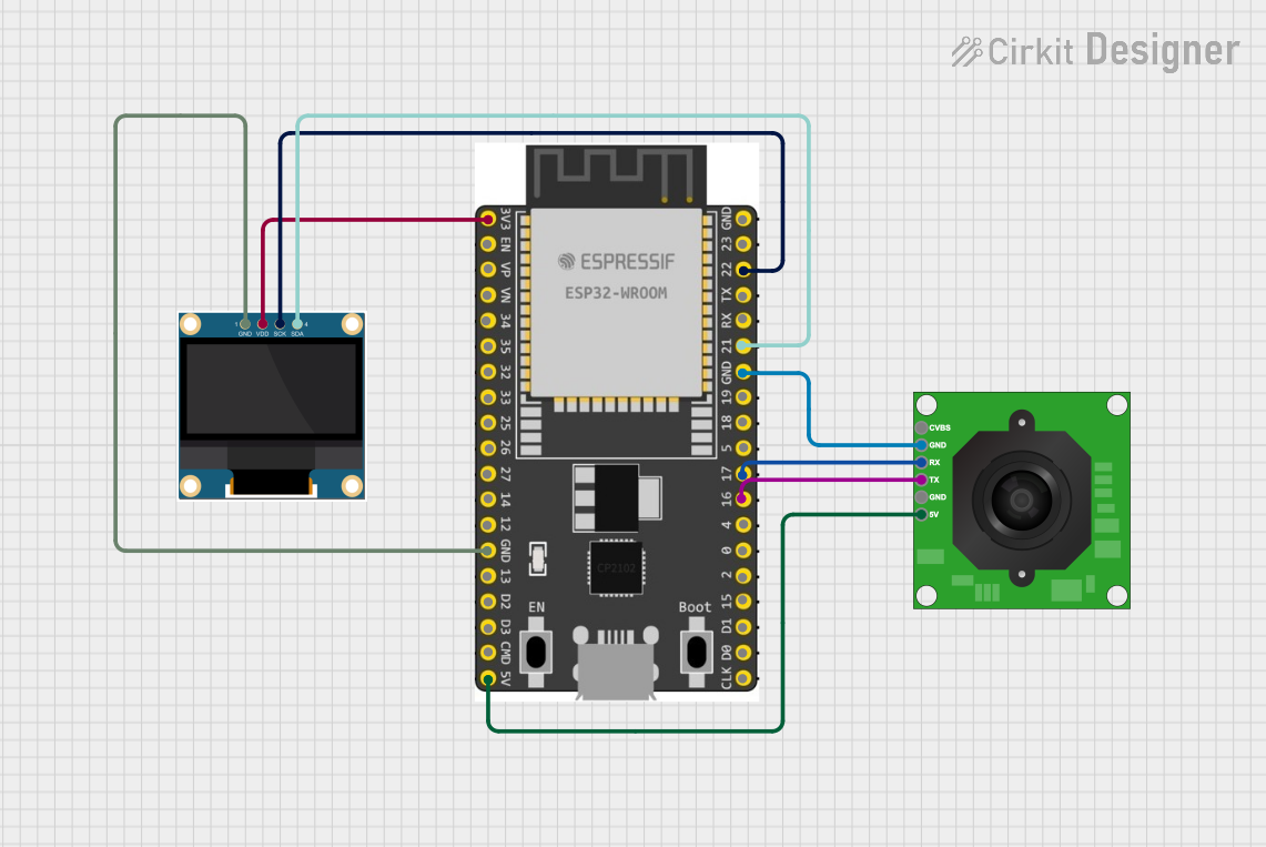 Open Project in Cirkit Designer
Explore Projects Built with ESP32-S3 CAM Development Board with OV3660 Camera Module
Open Project in Cirkit DesignerOpen Project in Cirkit DesignerOpen Project in Cirkit DesignerOpen Project in Cirkit DesignerCommon Applications and Use Cases
- Smart home devices (e.g., security cameras, video doorbells)
- IoT-enabled surveillance systems
- Real-time video streaming and monitoring
- Image recognition and processing for AI/ML applications
- Robotics and automation systems
- Educational and prototyping projects
Technical Specifications
Key Technical Details
| Parameter | Specification |
|---|---|
| Microcontroller | ESP32-S3 (Xtensa® 32-bit LX7 dual-core processor) |
| Camera Module | OV3660 (3MP resolution, supports JPEG and YUV formats) |
| Wireless Connectivity | Wi-Fi 802.11 b/g/n, Bluetooth 5.0 LE |
| Flash Memory | 8 MB PSRAM, 16 MB Flash |
| Operating Voltage | 3.3V |
| Power Supply Input | 5V via USB-C or external power source |
| GPIO Pins | 21 (including UART, SPI, I2C, PWM, ADC, and DAC) |
| Image Output Formats | JPEG, BMP, YUV |
| Dimensions | 40mm x 27mm |
| Operating Temperature Range | -40°C to 85°C |
Pin Configuration and Descriptions
The ESP32-S3 CAM Development Board features a compact pinout. Below is the pin configuration:
| Pin Name | Type | Description |
|---|---|---|
| 3V3 | Power | 3.3V power output |
| GND | Power | Ground connection |
| GPIO0 | Digital I/O | General-purpose I/O, used for boot mode selection |
| GPIO1 | Digital I/O | General-purpose I/O |
| GPIO2 | Digital I/O | General-purpose I/O |
| GPIO3 | Digital I/O | General-purpose I/O |
| GPIO4 | Digital I/O | General-purpose I/O |
| GPIO5 | Digital I/O | General-purpose I/O |
| GPIO12 | Digital I/O | General-purpose I/O |
| GPIO13 | Digital I/O | General-purpose I/O |
| GPIO14 | Digital I/O | General-purpose I/O |
| GPIO15 | Digital I/O | General-purpose I/O |
| GPIO16 | Digital I/O | General-purpose I/O |
| GPIO17 | Digital I/O | General-purpose I/O |
| GPIO18 | Digital I/O | General-purpose I/O |
| GPIO19 | Digital I/O | General-purpose I/O |
| GPIO20 | Digital I/O | General-purpose I/O |
| GPIO21 | Digital I/O | General-purpose I/O |
| TXD0 | UART TX | UART transmit pin |
| RXD0 | UART RX | UART receive pin |
| USB-C | Power/USB | USB-C port for power and programming |
Usage Instructions
How to Use the Component in a Circuit
Powering the Board:
- Connect the board to a 5V power source using the USB-C port or an external power supply.
- Ensure the power supply provides sufficient current (at least 500mA) for stable operation.
Programming the Board:
- Use the USB-C port to connect the board to your computer.
- Install the necessary drivers for the ESP32-S3 if not already installed.
- Use the Arduino IDE or Espressif's ESP-IDF for programming.
Connecting the Camera:
- The OV3660 camera module is pre-attached to the board. Ensure the ribbon cable is securely connected to the camera interface.
GPIO Usage:
- Use the GPIO pins for interfacing with external sensors, actuators, or other peripherals.
- Refer to the pin configuration table for specific pin functions.
Wi-Fi and Bluetooth Setup:
- Configure Wi-Fi and Bluetooth settings in your code to enable wireless communication.
Important Considerations and Best Practices
- Power Supply: Always use a stable power source to avoid unexpected resets or malfunctions.
- Camera Module: Handle the OV3660 camera module with care to avoid damaging the lens or ribbon cable.
- Heat Management: The ESP32-S3 may generate heat during operation. Ensure proper ventilation or use a heatsink if necessary.
- Firmware Updates: Regularly update the firmware to benefit from the latest features and bug fixes.
Example Code for Arduino UNO Integration
Below is an example code snippet to capture an image using the ESP32-S3 CAM and stream it over Wi-Fi:
#include <WiFi.h>
#include <esp_camera.h>

// Replace with your Wi-Fi credentials
const char* ssid = "Your_SSID";
const char* password = "Your_PASSWORD";

// Camera configuration
#define PWDN_GPIO_NUM    -1
#define RESET_GPIO_NUM   -1
#define XCLK_GPIO_NUM    0
#define SIOD_GPIO_NUM    26
#define SIOC_GPIO_NUM    27
#define Y9_GPIO_NUM      35
#define Y8_GPIO_NUM      34
#define Y7_GPIO_NUM      39
#define Y6_GPIO_NUM      36
#define Y5_GPIO_NUM      21
#define Y4_GPIO_NUM      19
#define Y3_GPIO_NUM      18
#define Y2_GPIO_NUM      5
#define VSYNC_GPIO_NUM   25
#define HREF_GPIO_NUM    23
#define PCLK_GPIO_NUM    22

void setup() {
  Serial.begin(115200);

  // Connect to Wi-Fi
  WiFi.begin(ssid, password);
  while (WiFi.status() != WL_CONNECTED) {
    delay(500);
    Serial.print(".");
  }
  Serial.println("\nWi-Fi connected");

  // Initialize the camera
  camera_config_t config;
  config.ledc_channel = LEDC_CHANNEL_0;
  config.ledc_timer = LEDC_TIMER_0;
  config.pin_d0 = Y2_GPIO_NUM;
  config.pin_d1 = Y3_GPIO_NUM;
  config.pin_d2 = Y4_GPIO_NUM;
  config.pin_d3 = Y5_GPIO_NUM;
  config.pin_d4 = Y6_GPIO_NUM;
  config.pin_d5 = Y7_GPIO_NUM;
  config.pin_d6 = Y8_GPIO_NUM;
  config.pin_d7 = Y9_GPIO_NUM;
  config.pin_xclk = XCLK_GPIO_NUM;
  config.pin_pclk = PCLK_GPIO_NUM;
  config.pin_vsync = VSYNC_GPIO_NUM;
  config.pin_href = HREF_GPIO_NUM;
  config.pin_sscb_sda = SIOD_GPIO_NUM;
  config.pin_sscb_scl = SIOC_GPIO_NUM;
  config.pin_pwdn = PWDN_GPIO_NUM;
  config.pin_reset = RESET_GPIO_NUM;
  config.xclk_freq_hz = 20000000;
  config.pixel_format = PIXFORMAT_JPEG;

  if (!esp_camera_init(&config)) {
    Serial.println("Camera initialized successfully");
  } else {
    Serial.println("Camera initialization failed");
  }
}

void loop() {
  // Capture an image
  camera_fb_t* fb = esp_camera_fb_get();
  if (!fb) {
    Serial.println("Failed to capture image");
    return;
  }

  // Print image size
  Serial.printf("Captured image size: %u bytes\n", fb->len);

  // Free the frame buffer
  esp_camera_fb_return(fb);

  delay(5000); // Capture an image every 5 seconds
}
Troubleshooting and FAQs
Common Issues and Solutions
Board Not Detected by Computer:
- Ensure the USB-C cable is properly connected and supports data transfer.
- Install the correct USB drivers for the ESP32-S3.
Camera Initialization Fails:
- Check the ribbon cable connection between the camera module and the board.
- Ensure the camera configuration in the code matches the hardware setup.
Wi-Fi Connection Issues:
- Verify the SSID and password in your code.
- Ensure the Wi-Fi network is within range and operational.
Overheating:
- Provide adequate ventilation or use a heatsink to dissipate heat.
FAQs
Q: Can I use this board for AI/ML applications?
A: Yes, the ESP32-S3 supports AI/ML frameworks like TensorFlow Lite for Microcontrollers.Q: What is the maximum resolution of the OV3660 camera?
A: The OV3660 supports up to 3MP resolution.Q: Can I power the board using a battery?
A