Cirkit Designer Logo
Cirkit Designer
Your all-in-one circuit design IDE
Home / 
Component Documentation

How to Use powerbox Pionner: Examples, Pinouts, and Specs

Image of powerbox Pionner
Cirkit Designer LogoDesign with powerbox Pionner in Cirkit Designer

Introduction

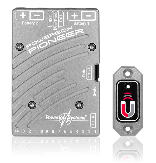
The Powerbox Pioneer, manufactured by Powerbox System, is a power distribution unit designed to manage and supply electrical power to various devices in a circuit. It ensures stable voltage and current levels, making it an essential component for applications requiring reliable power delivery. The Powerbox Pioneer is commonly used in industrial automation, robotics, and embedded systems, where consistent power distribution is critical.

Explore Projects Built with powerbox Pionner

Use Cirkit Designer to design, explore, and prototype these projects online. Some projects support real-time simulation. Click "Open Project" to start designing instantly!
Battery-Powered Adjustable Voltage Regulator with Li-ion 18650 Batteries and BMS
Image of mini ups: A project utilizing powerbox Pionner in a practical application
This circuit is a power management system that uses four Li-ion 18650 batteries connected to a 2S 30A BMS for battery management and protection. The system includes step-up and step-down voltage regulators to provide adjustable output voltages, controlled by a rocker switch, and multiple DC jacks for power input and output.
Cirkit Designer LogoOpen Project in Cirkit Designer
Battery-Powered UPS with Step-Down Buck Converter and BMS
Image of Mini ups: A project utilizing powerbox Pionner in a practical application
This circuit is a power management system that steps down a 240V AC input to a lower DC voltage using a buck converter, which then powers a 40W UPS. The UPS is controlled by a rocker switch and is backed up by a battery management system (BMS) connected to three 3.7V batteries in series, ensuring continuous power supply.
Cirkit Designer LogoOpen Project in Cirkit Designer
Bluetooth Audio Receiver with Battery-Powered Amplifier and Loudspeakers
Image of speaker bluetooh portable: A project utilizing powerbox Pionner in a practical application
This circuit is a Bluetooth-enabled audio system powered by a rechargeable 18650 Li-ion battery. It includes a TP4056 module for battery charging and protection, a PAM8403 amplifier with volume control to drive two loudspeakers, and a Bluetooth audio receiver to wirelessly receive audio signals.
Cirkit Designer LogoOpen Project in Cirkit Designer
Battery-Powered FPV Drone with Telemetry and Dual Motor Control
Image of Krul': A project utilizing powerbox Pionner in a practical application
This circuit appears to be a power distribution and control system for a vehicle with two motorized wheels, possibly a drone or a robot. It includes a lipo battery connected to a Power Distribution Board (PDB) that distributes power to two Electronic Speed Controllers (ESCs) which in turn control the speed and direction of the motors. The system also integrates a flight controller (H743-SLIM V3) for managing various peripherals including GPS, FPV camera system, and a telemetry link (ExpressLRS).
Cirkit Designer LogoOpen Project in Cirkit Designer

Explore Projects Built with powerbox Pionner

Use Cirkit Designer to design, explore, and prototype these projects online. Some projects support real-time simulation. Click "Open Project" to start designing instantly!
Image of mini ups: A project utilizing powerbox Pionner in a practical application
Battery-Powered Adjustable Voltage Regulator with Li-ion 18650 Batteries and BMS
This circuit is a power management system that uses four Li-ion 18650 batteries connected to a 2S 30A BMS for battery management and protection. The system includes step-up and step-down voltage regulators to provide adjustable output voltages, controlled by a rocker switch, and multiple DC jacks for power input and output.
Cirkit Designer LogoOpen Project in Cirkit Designer
Image of Mini ups: A project utilizing powerbox Pionner in a practical application
Battery-Powered UPS with Step-Down Buck Converter and BMS
This circuit is a power management system that steps down a 240V AC input to a lower DC voltage using a buck converter, which then powers a 40W UPS. The UPS is controlled by a rocker switch and is backed up by a battery management system (BMS) connected to three 3.7V batteries in series, ensuring continuous power supply.
Cirkit Designer LogoOpen Project in Cirkit Designer
Image of speaker bluetooh portable: A project utilizing powerbox Pionner in a practical application
Bluetooth Audio Receiver with Battery-Powered Amplifier and Loudspeakers
This circuit is a Bluetooth-enabled audio system powered by a rechargeable 18650 Li-ion battery. It includes a TP4056 module for battery charging and protection, a PAM8403 amplifier with volume control to drive two loudspeakers, and a Bluetooth audio receiver to wirelessly receive audio signals.
Cirkit Designer LogoOpen Project in Cirkit Designer
Image of Krul': A project utilizing powerbox Pionner in a practical application
Battery-Powered FPV Drone with Telemetry and Dual Motor Control
This circuit appears to be a power distribution and control system for a vehicle with two motorized wheels, possibly a drone or a robot. It includes a lipo battery connected to a Power Distribution Board (PDB) that distributes power to two Electronic Speed Controllers (ESCs) which in turn control the speed and direction of the motors. The system also integrates a flight controller (H743-SLIM V3) for managing various peripherals including GPS, FPV camera system, and a telemetry link (ExpressLRS).
Cirkit Designer LogoOpen Project in Cirkit Designer

Common Applications and Use Cases

  • Powering multiple devices in embedded systems
  • Voltage regulation in robotics and automation
  • Power management in IoT devices
  • Distribution of power in multi-device circuits

Technical Specifications

Key Technical Details

Parameter Value
Input Voltage Range 6V to 24V DC
Output Voltage 5V DC (regulated)
Maximum Output Current 3A
Efficiency Up to 92%
Operating Temperature -20°C to 70°C
Dimensions 50mm x 30mm x 15mm
Weight 25g
Protection Features Overcurrent, Overvoltage,
Short Circuit Protection

Pin Configuration and Descriptions

Pin Number Pin Name Description
1 VIN Input voltage (6V to 24V DC)
2 GND Ground connection
3 VOUT Regulated 5V DC output
4 STATUS Status pin (indicates power status: HIGH = OK)
5 ENABLE Enable pin (active HIGH to enable output)

Usage Instructions

How to Use the Powerbox Pioneer in a Circuit

  1. Connect Input Voltage: Connect the input voltage (6V to 24V DC) to the VIN pin. Ensure the input voltage is within the specified range to avoid damage.
  2. Connect Ground: Connect the GND pin to the ground of your circuit.
  3. Connect Output: Use the VOUT pin to power your devices. The output voltage is regulated at 5V DC.
  4. Enable the Output: To enable the output, set the ENABLE pin to HIGH. If left floating or set to LOW, the output will be disabled.
  5. Monitor Status: Use the STATUS pin to monitor the power status. A HIGH signal indicates normal operation, while a LOW signal indicates a fault.

Important Considerations and Best Practices

  • Input Voltage: Always ensure the input voltage is within the specified range (6V to 24V DC). Exceeding this range may damage the component.
  • Heat Dissipation: If operating at maximum current (3A), ensure proper ventilation or heat sinking to prevent overheating.
  • Load Capacity: Do not exceed the maximum output current of 3A to avoid triggering overcurrent protection.
  • Enable Pin: If the ENABLE pin is not used, connect it to a HIGH signal to keep the output active.

Example: Connecting to an Arduino UNO

The Powerbox Pioneer can be used to power an Arduino UNO and other peripherals. Below is an example circuit and code:

Circuit Connections

  • Connect the VIN pin of the Powerbox Pioneer to a 12V DC power supply.
  • Connect the GND pin to the ground of the Arduino UNO.
  • Connect the VOUT pin to the 5V pin of the Arduino UNO.
  • Optionally, connect the STATUS pin to a digital input pin on the Arduino to monitor power status.

Arduino Code Example

// Define the pin connected to the STATUS pin of Powerbox Pioneer
const int statusPin = 2;

void setup() {
  pinMode(statusPin, INPUT); // Set the STATUS pin as input
  Serial.begin(9600);        // Initialize serial communication
}

void loop() {
  int status = digitalRead(statusPin); // Read the STATUS pin
  if (status == HIGH) {
    Serial.println("Powerbox Pioneer: Power is stable.");
  } else {
    Serial.println("Powerbox Pioneer: Power fault detected!");
  }
  delay(1000); // Wait for 1 second before checking again
}

Troubleshooting and FAQs

Common Issues and Solutions

Issue Possible Cause Solution
No output voltage ENABLE pin is LOW or floating Set the ENABLE pin to HIGH.
Output voltage is unstable Input voltage is out of range Ensure input voltage is between 6V-24V.
Overheating Exceeding maximum current (3A) Reduce load or improve heat dissipation.
STATUS pin reads LOW Fault condition (e.g., overcurrent) Check for short circuits or excessive load.

FAQs

  1. Can the Powerbox Pioneer output voltage be adjusted?
    No, the output voltage is fixed at 5V DC.

  2. What happens if the input voltage exceeds 24V?
    The overvoltage protection will activate, and the unit may shut down to prevent damage.

  3. Can I use the Powerbox Pioneer with a battery?
    Yes, as long as the battery voltage is within the 6V to 24V range.

  4. Is the Powerbox Pioneer suitable for outdoor use?
    The component is not weatherproof. Use it in a protected environment or within an enclosure.