Cirkit Designer Logo
Cirkit Designer
Your all-in-one circuit design IDE
Home / 
Component Documentation

How to Use MQ135: Examples, Pinouts, and Specs

Image of MQ135
Cirkit Designer LogoDesign with MQ135 in Cirkit Designer

Introduction

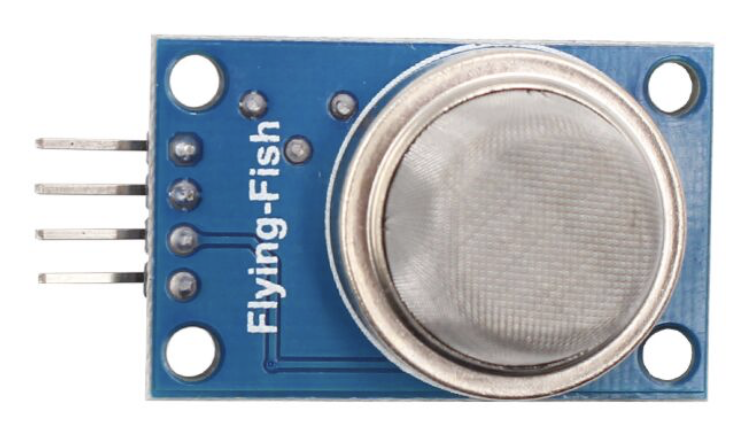
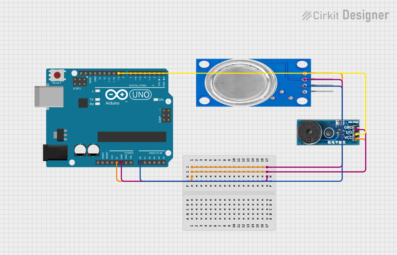
The MQ135 is a versatile gas sensor designed to detect a wide range of gases, including ammonia, benzene, alcohol, and smoke. Manufactured by ESP32 with the part ID 001, this sensor operates on the principle of resistive change when exposed to target gases. It provides an analog output that can be easily interfaced with microcontrollers, making it ideal for air quality monitoring and environmental sensing applications.

Explore Projects Built with MQ135

Use Cirkit Designer to design, explore, and prototype these projects online. Some projects support real-time simulation. Click "Open Project" to start designing instantly!
Arduino UNO Based Air Quality Monitoring and GSM Notification System
Image of Arduino wild: A project utilizing MQ135 in a practical application
This circuit features an Arduino UNO microcontroller interfaced with an MQ135 air quality sensor, an MPU-6050 accelerometer/gyroscope, a SIM900A GSM communication module, and a buzzer. The Arduino reads analog data from the MQ135 sensor and communicates with the MPU-6050 via I2C, while also controlling the buzzer and handling serial communication with the SIM900A module. The purpose of this circuit is likely to monitor air quality and motion, provide alerts through the buzzer, and enable remote communication via GSM.
Cirkit Designer LogoOpen Project in Cirkit Designer
Arduino UNO Air Quality Monitor with LED Indicator and Piezo Speaker
Image of EXP-2. LED & Buzzer ON/OFF Using MQ-135 Sensor & Arduino: A project utilizing MQ135 in a practical application
This circuit uses an Arduino UNO to monitor air quality via an MQ 135 sensor and provides visual and auditory feedback using an LED and a piezo speaker. The Arduino is powered by a MAHIR 7.0 power supply, and the LED and speaker are controlled through digital pins D13 and D12, respectively.
Cirkit Designer LogoOpen Project in Cirkit Designer
Arduino UNO Based Gas Detection and GSM Alert System
Image of Copy of Copy of gas sensor: A project utilizing MQ135 in a practical application
This circuit is designed to monitor air quality using an MQ135 sensor and provide visual and audible alerts. It features an Arduino UNO microcontroller interfaced with a GSM module for communication, an I2C LCD for display, and LEDs and a buzzer for local alerts. The Arduino runs embedded code to read the MQ135 sensor data, display air quality index (AQI) on the LCD, and trigger SMS and call alerts via the GSM module when gas is detected above a certain threshold.
Cirkit Designer LogoOpen Project in Cirkit Designer
Arduino UNO Based Air Quality Monitor with Buzzer Alert
Image of smoke detector: A project utilizing MQ135 in a practical application
This circuit consists of an Arduino UNO microcontroller connected to an MQ135 air quality sensor and a buzzer module. The MQ135 sensor's analog output (A0) is connected to the Arduino's analog input (A0) to monitor air quality, while the buzzer's I/O pin is connected to the Arduino's digital pin (D9) to potentially alert based on sensor readings. The Arduino, sensor, and buzzer share a common power supply (5V) and ground (GND), indicating that the Arduino controls both the sensor data acquisition and the buzzer activation.
Cirkit Designer LogoOpen Project in Cirkit Designer

Explore Projects Built with MQ135

Use Cirkit Designer to design, explore, and prototype these projects online. Some projects support real-time simulation. Click "Open Project" to start designing instantly!
Image of Arduino wild: A project utilizing MQ135 in a practical application
Arduino UNO Based Air Quality Monitoring and GSM Notification System
This circuit features an Arduino UNO microcontroller interfaced with an MQ135 air quality sensor, an MPU-6050 accelerometer/gyroscope, a SIM900A GSM communication module, and a buzzer. The Arduino reads analog data from the MQ135 sensor and communicates with the MPU-6050 via I2C, while also controlling the buzzer and handling serial communication with the SIM900A module. The purpose of this circuit is likely to monitor air quality and motion, provide alerts through the buzzer, and enable remote communication via GSM.
Cirkit Designer LogoOpen Project in Cirkit Designer
Image of EXP-2. LED & Buzzer ON/OFF Using MQ-135 Sensor & Arduino: A project utilizing MQ135 in a practical application
Arduino UNO Air Quality Monitor with LED Indicator and Piezo Speaker
This circuit uses an Arduino UNO to monitor air quality via an MQ 135 sensor and provides visual and auditory feedback using an LED and a piezo speaker. The Arduino is powered by a MAHIR 7.0 power supply, and the LED and speaker are controlled through digital pins D13 and D12, respectively.
Cirkit Designer LogoOpen Project in Cirkit Designer
Image of Copy of Copy of gas sensor: A project utilizing MQ135 in a practical application
Arduino UNO Based Gas Detection and GSM Alert System
This circuit is designed to monitor air quality using an MQ135 sensor and provide visual and audible alerts. It features an Arduino UNO microcontroller interfaced with a GSM module for communication, an I2C LCD for display, and LEDs and a buzzer for local alerts. The Arduino runs embedded code to read the MQ135 sensor data, display air quality index (AQI) on the LCD, and trigger SMS and call alerts via the GSM module when gas is detected above a certain threshold.
Cirkit Designer LogoOpen Project in Cirkit Designer
Image of smoke detector: A project utilizing MQ135 in a practical application
Arduino UNO Based Air Quality Monitor with Buzzer Alert
This circuit consists of an Arduino UNO microcontroller connected to an MQ135 air quality sensor and a buzzer module. The MQ135 sensor's analog output (A0) is connected to the Arduino's analog input (A0) to monitor air quality, while the buzzer's I/O pin is connected to the Arduino's digital pin (D9) to potentially alert based on sensor readings. The Arduino, sensor, and buzzer share a common power supply (5V) and ground (GND), indicating that the Arduino controls both the sensor data acquisition and the buzzer activation.
Cirkit Designer LogoOpen Project in Cirkit Designer

Common Applications

  • Air quality monitoring systems
  • Industrial gas detection
  • Smoke and fire detection
  • Environmental pollution monitoring
  • Smart home automation for air quality control

Technical Specifications

The MQ135 sensor is designed for ease of use and reliable performance. Below are its key technical details:

Parameter Value
Operating Voltage 5V DC
Load Resistance (RL) 10 kΩ (typical)
Heating Voltage (VH) 5V ± 0.2V
Heating Current (IH) ≤ 120 mA
Detection Range 10 ppm to 1000 ppm
Preheat Time ≥ 24 hours for stable output
Analog Output Voltage 0V to 5V
Operating Temperature -20°C to 50°C
Humidity Range ≤ 95% RH
Dimensions 32mm x 20mm x 22mm

Pin Configuration and Descriptions

The MQ135 sensor typically comes with a 4-pin interface. Below is the pinout description:

Pin Name Description
1 VCC Power supply pin (5V DC)
2 GND Ground pin
3 AOUT Analog output pin; provides a voltage proportional
to the concentration of detected gases
4 DOUT Digital output pin; triggers when gas concentration
exceeds a preset threshold

Usage Instructions

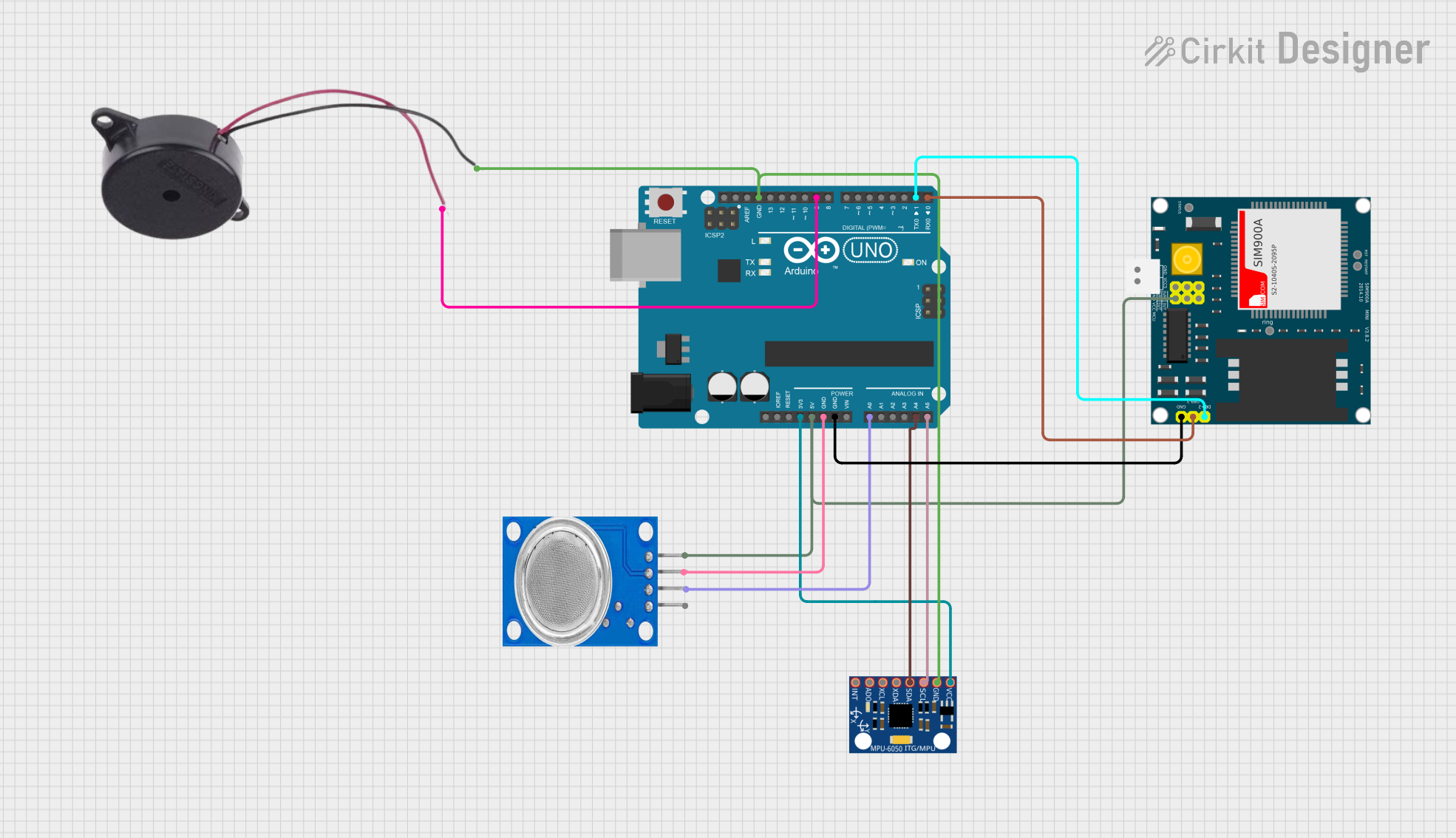
The MQ135 sensor is straightforward to use in a circuit. Follow the steps below to integrate it into your project:

Circuit Connection

  1. Connect the VCC pin to a 5V power supply.
  2. Connect the GND pin to the ground of your circuit.
  3. Connect the AOUT pin to an analog input pin of your microcontroller (e.g., Arduino UNO).
  4. Optionally, connect the DOUT pin to a digital input pin if you want to use the threshold-based digital output.

Important Considerations

  • Preheating: The sensor requires a preheating time of at least 24 hours for accurate readings. During this time, the internal heater stabilizes the sensor's performance.
  • Calibration: For precise measurements, calibrate the sensor in a clean air environment to establish a baseline reading.
  • Power Supply: Ensure a stable 5V power supply to avoid fluctuations in the sensor's output.
  • Ventilation: Place the sensor in a well-ventilated area to avoid saturation and ensure accurate gas detection.

Example Code for Arduino UNO

Below is an example of how to use the MQ135 sensor with an Arduino UNO to read analog values:

// MQ135 Gas Sensor Example Code
// This code reads the analog output of the MQ135 sensor and prints the value
// to the Serial Monitor. Ensure the sensor is connected to the correct pins.

const int MQ135_PIN = A0; // Connect AOUT pin of MQ135 to Arduino analog pin A0

void setup() {
  Serial.begin(9600); // Initialize serial communication at 9600 baud
  Serial.println("MQ135 Gas Sensor Test");
}

void loop() {
  int sensorValue = analogRead(MQ135_PIN); // Read analog value from MQ135
  float voltage = sensorValue * (5.0 / 1023.0); // Convert to voltage (0-5V)
  
  // Print the raw sensor value and voltage to the Serial Monitor
  Serial.print("Sensor Value: ");
  Serial.print(sensorValue);
  Serial.print(" | Voltage: ");
  Serial.print(voltage);
  Serial.println(" V");
  
  delay(1000); // Wait for 1 second before the next reading
}

Best Practices

  • Use a load resistor (RL) of 10 kΩ for typical applications.
  • Avoid exposing the sensor to high concentrations of corrosive gases for extended periods, as this may damage the sensor.
  • Place the sensor in a vertical orientation to ensure proper airflow.

Troubleshooting and FAQs

Common Issues and Solutions

  1. No Output or Incorrect Readings

    • Cause: Insufficient preheating time.
    • Solution: Allow the sensor to preheat for at least 24 hours before use.
  2. Fluctuating Readings

    • Cause: Unstable power supply or environmental interference.
    • Solution: Use a regulated 5V power supply and ensure the sensor is placed in a stable environment.
  3. Sensor Saturation

    • Cause: Prolonged exposure to high concentrations of target gases.
    • Solution: Remove the sensor from the high-concentration environment and allow it to recover in clean air.
  4. Digital Output Not Triggering

    • Cause: Threshold not properly set on the onboard potentiometer.
    • Solution: Adjust the potentiometer to set the desired gas concentration threshold.

FAQs

Q1: Can the MQ135 detect multiple gases simultaneously?
A1: Yes, the MQ135 can detect a variety of gases, but it does not differentiate between them. It provides a combined analog output based on the total concentration of detected gases.

Q2: How do I calibrate the MQ135 sensor?
A2: To calibrate, expose the sensor to clean air and record the baseline analog output. Use this value to calculate gas concentrations in your application.

Q3: Can I use the MQ135 with a 3.3V microcontroller?
A3: The MQ135 requires a 5V power supply for proper operation. However, you can use a voltage divider or level shifter to interface its output with a 3.3V microcontroller.

Q4: What is the lifespan of the MQ135 sensor?
A4: The MQ135 has a typical lifespan of 2-3 years under normal operating conditions. Regular maintenance and proper usage can extend its life.

By following this documentation, you can effectively integrate the MQ135 gas sensor into your projects and ensure reliable performance.