How to Use DC Motor Gearbox N20: Examples, Pinouts, and Specs
Introduction
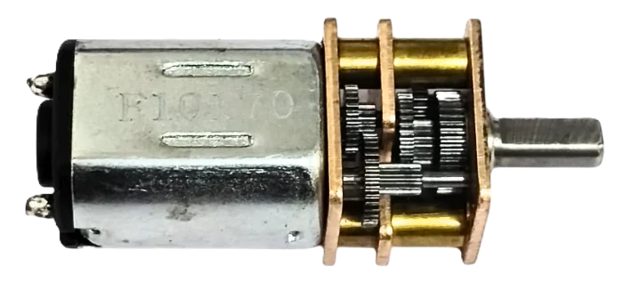
The DC Motor Gearbox N20 (Manufacturer Part ID: N20-12V-300RPM) is a compact DC motor with an integrated gearbox, designed to deliver high torque at low speeds. Manufactured by GAONENG / JGA (or generic if unspecified), this motor is widely used in robotics, automation, and small-scale mechanical systems. Its small size and efficient design make it ideal for applications requiring precise control and reliable performance.
Explore Projects Built with DC Motor Gearbox N20
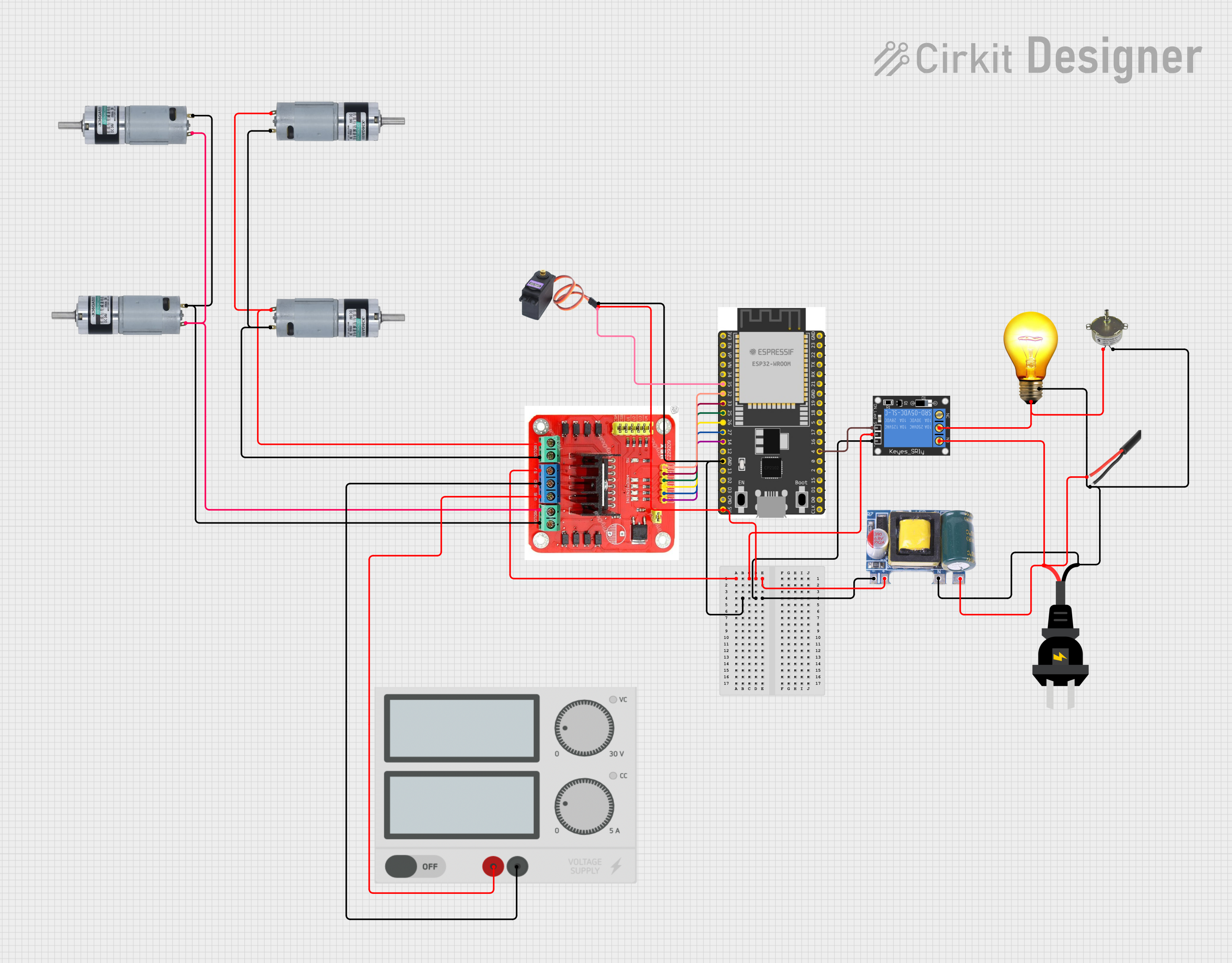
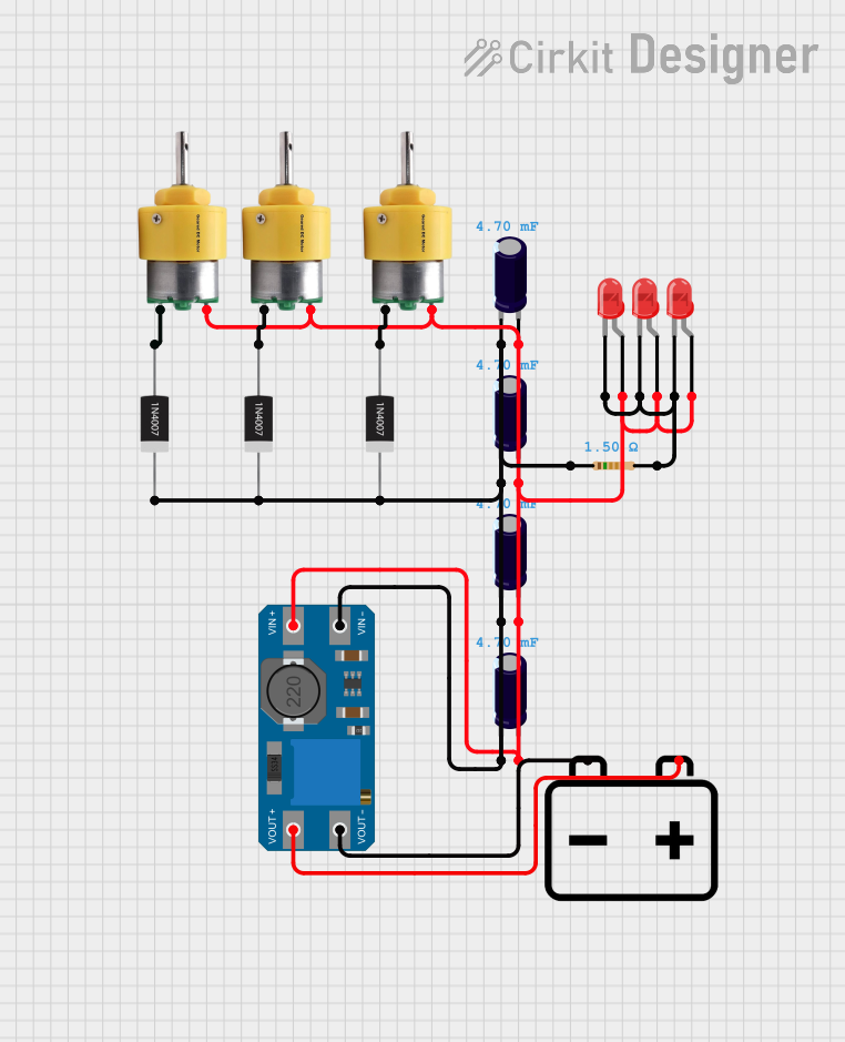

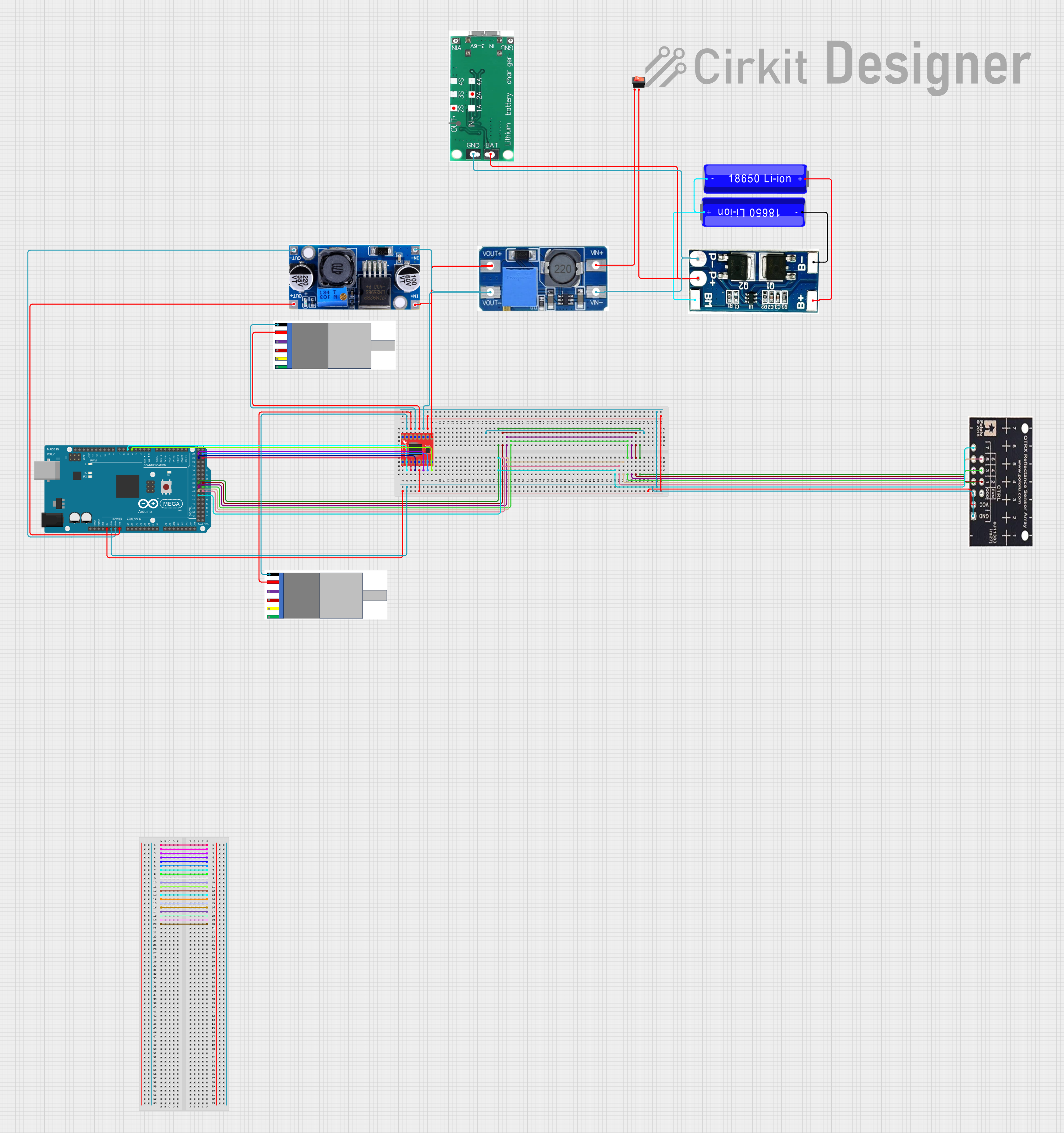
Explore Projects Built with DC Motor Gearbox N20
Common Applications
- Robotics (e.g., driving wheels or robotic arms)
- Automated systems (e.g., conveyor belts, small actuators)
- DIY projects (e.g., model cars, smart home devices)
- Educational kits for learning about motors and gear systems
Technical Specifications
Below are the key technical details for the N20-12V-300RPM motor:
| Parameter | Value |
|---|---|
| Operating Voltage | 6V - 12V |
| Rated Voltage | 12V |
| No-Load Speed | 300 RPM |
| Stall Torque | ~1.2 kg·cm (at 12V) |
| Stall Current | ~0.8A (at 12V) |
| Gear Ratio | 1:50 |
| Motor Dimensions | 12mm x 10mm x 26mm |
| Shaft Diameter | 3mm |
| Shaft Length | 10mm |
| Weight | ~10g |
Pin Configuration and Descriptions
The N20 motor has two terminals for electrical connections:
| Pin | Description |
|---|---|
| Pin 1 | Positive terminal (V+) |
| Pin 2 | Negative terminal (GND) |
Note: Reversing the polarity of the terminals will reverse the motor's rotation direction.
Usage Instructions
How to Use the Component in a Circuit
- Power Supply: Connect the motor to a DC power source within the operating voltage range (6V to 12V). A 12V supply is recommended for optimal performance.
- Polarity Control: Use an H-bridge motor driver (e.g., L298N or L293D) to control the motor's direction and speed. This allows for forward and reverse rotation.
- PWM Speed Control: To adjust the motor speed, use a PWM (Pulse Width Modulation) signal from a microcontroller (e.g., Arduino UNO).
- Mounting: Secure the motor using screws or a motor bracket to prevent vibration during operation.
Important Considerations and Best Practices
- Avoid Overloading: Do not exceed the stall torque or stall current to prevent motor damage.
- Heat Management: Prolonged operation at high loads may cause the motor to overheat. Allow for adequate cooling.
- Power Supply: Use a stable DC power source to avoid voltage fluctuations that could harm the motor.
- Noise Suppression: Add capacitors (e.g., 0.1µF) across the motor terminals to reduce electrical noise.
Example: Connecting to an Arduino UNO
Below is an example of controlling the N20 motor using an Arduino UNO and an L298N motor driver:
// Example: Controlling N20 Motor with Arduino UNO and L298N Motor Driver

// Define motor control pins
const int ENA = 9;  // PWM pin for speed control
const int IN1 = 7;  // Direction control pin 1
const int IN2 = 8;  // Direction control pin 2

void setup() {
  // Set motor control pins as outputs
  pinMode(ENA, OUTPUT);
  pinMode(IN1, OUTPUT);
  pinMode(IN2, OUTPUT);
}

void loop() {
  // Rotate motor forward at 50% speed
  analogWrite(ENA, 128);  // Set PWM duty cycle (0-255)
  digitalWrite(IN1, HIGH);
  digitalWrite(IN2, LOW);
  delay(2000);  // Run for 2 seconds

  // Stop the motor
  analogWrite(ENA, 0);
  delay(1000);  // Pause for 1 second

  // Rotate motor backward at 75% speed
  analogWrite(ENA, 192);  // Set PWM duty cycle (0-255)
  digitalWrite(IN1, LOW);
  digitalWrite(IN2, HIGH);
  delay(2000);  // Run for 2 seconds

  // Stop the motor
  analogWrite(ENA, 0);
  delay(1000);  // Pause for 1 second
}
Note: Ensure the motor driver is powered appropriately and the motor connections are secure.
Troubleshooting and FAQs
Common Issues and Solutions
Motor Does Not Spin
- Cause: Insufficient power supply or loose connections.
- Solution: Verify the power source voltage and ensure all connections are secure.
Motor Spins in the Wrong Direction
- Cause: Incorrect polarity or control signal.
- Solution: Reverse the motor terminals or adjust the control signals.
Motor Overheats
- Cause: Prolonged operation at high loads or insufficient cooling.
- Solution: Reduce the load or provide adequate cooling.
Excessive Noise or Vibration
- Cause: Loose mounting or electrical noise.
- Solution: Secure the motor properly and add capacitors across the terminals.
FAQs
Q: Can the motor operate below 6V?
A: While the motor may run at lower voltages, performance (speed and torque) will be significantly reduced.Q: Can I use the motor without a driver?
A: Yes, but a motor driver is recommended for precise control of speed and direction.Q: What is the lifespan of the motor?
A: The lifespan depends on usage conditions, but proper handling and avoiding overloads can extend its life.
This concludes the documentation for the DC Motor Gearbox N20. For further assistance, refer to the manufacturer's datasheet or contact technical support.