How to Use ESP32 DOIT DEV KIT2: Examples, Pinouts, and Specs
Introduction
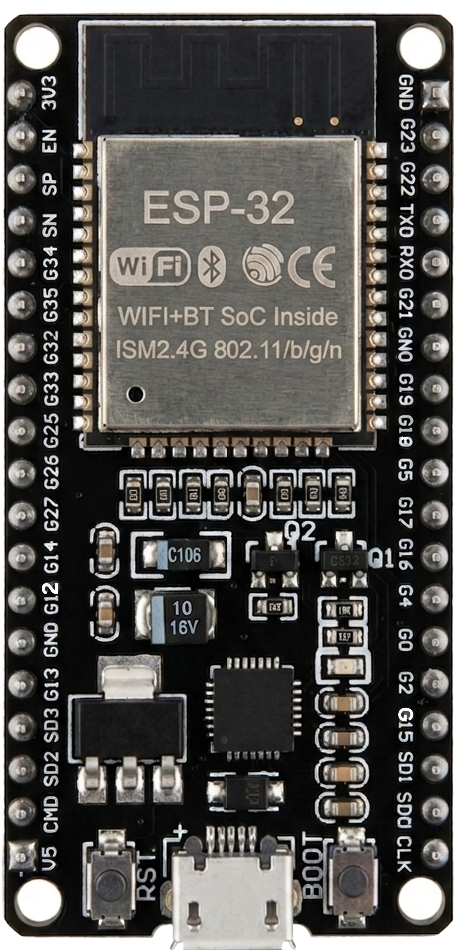
The ESP32 DOIT DEV KIT V1, manufactured by Espressif Systems, is a versatile development board built around the ESP32 chip. This board integrates Wi-Fi and Bluetooth capabilities, making it an excellent choice for Internet of Things (IoT) projects, smart home applications, and wireless communication systems. Its compact design, powerful processing capabilities, and extensive GPIO options make it suitable for both beginners and advanced developers.
Explore Projects Built with ESP32 DOIT DEV KIT2


Explore Projects Built with ESP32 DOIT DEV KIT2
Common Applications
- IoT devices and smart home automation
- Wireless sensor networks
- Robotics and control systems
- Wearable devices
- Prototyping and educational projects
Technical Specifications
Key Technical Details
| Parameter | Specification |
|---|---|
| Microcontroller | ESP32 (WIFI+BT SoC Inside) |
| Operating Voltage | 3.3V |
| Input Voltage (VIN) | 5V (via USB or external power supply) |
| Flash Memory | 4MB |
| SRAM | 520KB |
| Wi-Fi Standards | 802.11 b/g/n |
| Bluetooth Version | Bluetooth 4.2 + BLE |
| GPIO Pins | 30 (including ADC, DAC, PWM, I2C, SPI, UART) |
| ADC Resolution | 12-bit |
| DAC Resolution | 8-bit |
| Clock Speed | Up to 240 MHz |
| USB Interface | Micro-USB |
| Dimensions | 25.4mm x 51mm |
Pin Configuration and Descriptions
The ESP32 DOIT DEV KIT V1 features a total of 30 GPIO pins, which can be configured for various functions such as ADC, DAC, PWM, I2C, SPI, and UART. Below is the pinout description:
| Pin Number | Pin Name | Functionality |
|---|---|---|
| 1 | VIN | Input voltage (5V) |
| 2 | GND | Ground |
| 3 | 3V3 | 3.3V output |
| 4 | EN | Enable pin (active high) |
| 5 | IO0 | GPIO0, boot mode selection |
| 6 | IO2 | GPIO2, ADC, DAC |
| 7 | IO4 | GPIO4, ADC, PWM |
| 8 | IO5 | GPIO5, ADC, PWM |
| 9 | IO12 | GPIO12, ADC, PWM |
| 10 | IO13 | GPIO13, ADC, PWM |
| 11 | IO14 | GPIO14, ADC, PWM |
| 12 | IO15 | GPIO15, ADC, PWM |
| 13 | IO16 | GPIO16, UART RX |
| 14 | IO17 | GPIO17, UART TX |
| 15 | IO18 | GPIO18, SPI SCK |
| 16 | IO19 | GPIO19, SPI MISO |
| 17 | IO21 | GPIO21, I2C SDA |
| 18 | IO22 | GPIO22, I2C SCL |
| 19 | IO23 | GPIO23, SPI MOSI |
| 20 | IO25 | GPIO25, ADC, DAC |
| 21 | IO26 | GPIO26, ADC, DAC |
| 22 | IO27 | GPIO27, ADC, PWM |
| 23 | IO32 | GPIO32, ADC |
| 24 | IO33 | GPIO33, ADC |
| 25 | IO34 | GPIO34, ADC (input only) |
| 26 | IO35 | GPIO35, ADC (input only) |
| 27 | IO36 | GPIO36, ADC (input only) |
| 28 | IO39 | GPIO39, ADC (input only) |
Usage Instructions
How to Use the ESP32 DOIT DEV KIT V1 in a Circuit
Powering the Board:
- Connect the board to your computer using a Micro-USB cable. This will provide both power and a communication interface for programming.
- Alternatively, supply 5V to the VIN pin and GND for external power.
Programming the Board:
- Install the Arduino IDE and add the ESP32 board support package.
- Go to File > Preferences and add the following URL to the "Additional Board Manager URLs":
https://dl.espressif.com/dl/package_esp32_index.json - Open the Boards Manager (Tools > Board > Boards Manager), search for "ESP32," and install the package.
- Go to File > Preferences and add the following URL to the "Additional Board Manager URLs":
- Select the board as DOIT ESP32 DEVKIT V1 from the Tools menu.
- Connect the board to your computer and select the appropriate COM port.
- Install the Arduino IDE and add the ESP32 board support package.
Uploading Code:
- Write or load your code in the Arduino IDE.
- Click the upload button to flash the code onto the ESP32.
Example Code: Blinking an LED
The following example demonstrates how to blink an LED connected to GPIO2.
// Define the GPIO pin where the LED is connected
#define LED_PIN 2

void setup() {
  // Set the LED pin as an output
  pinMode(LED_PIN, OUTPUT);
}

void loop() {
  // Turn the LED on
  digitalWrite(LED_PIN, HIGH);
  delay(1000); // Wait for 1 second

  // Turn the LED off
  digitalWrite(LED_PIN, LOW);
  delay(1000); // Wait for 1 second
}
Important Considerations and Best Practices
- Voltage Levels: Ensure that all connected peripherals operate at 3.3V logic levels to avoid damaging the ESP32.
- Boot Mode: GPIO0 is used for boot mode selection. Avoid pulling it high during boot if you intend to upload code.
- Power Supply: Use a stable power source to avoid unexpected resets or instability.
- Wi-Fi and Bluetooth: Avoid placing the board in metal enclosures, as this can interfere with wireless communication.
Troubleshooting and FAQs
Common Issues and Solutions
Issue: The board is not detected by the computer.
Solution:- Ensure the USB cable is functional and supports data transfer.
- Install the necessary USB-to-serial drivers (e.g., CP2102 or CH340, depending on your board).
Issue: Code upload fails with a timeout error.
Solution:- Press and hold the BOOT button on the board while uploading the code.
- Check that the correct COM port is selected in the Arduino IDE.
Issue: Wi-Fi connection is unstable.
Solution:- Ensure the board is within range of the Wi-Fi router.
- Check for interference from other devices operating on the same frequency.
Issue: GPIO pins are not functioning as expected.
Solution:- Verify that the pins are not being used for other functions (e.g., boot mode).
- Check the pin configuration in your code.
FAQs
Q1: Can I power the ESP32 using a battery?
A1: Yes, you can power the board using a 3.7V LiPo battery connected to the VIN and GND pins. Ensure the battery voltage is regulated to avoid damage.
Q2: How do I reset the board?
A2: Press the EN button on the board to reset it.
Q3: Can I use the ESP32 with MicroPython?
A3: Yes, the ESP32 supports MicroPython. You can flash the MicroPython firmware onto the board and use a Python-based development environment.
Q4: What is the maximum current output of the 3.3V pin?
A4: The 3.3V pin can supply up to 500mA, depending on the input power source.
This concludes the documentation for the ESP32 DOIT DEV KIT V1.