How to Use UNO R4 MINI PRO: Examples, Pinouts, and Specs
Introduction
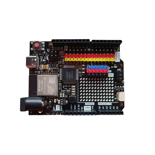
The UNO R4 MINI PRO is a compact microcontroller board developed by Arduino, featuring the ATmega328P microcontroller. Designed for seamless integration into a wide range of projects, it offers a balance of performance, versatility, and ease of use. The board is equipped with digital and analog I/O pins, USB connectivity, and full compatibility with the Arduino IDE, making it an excellent choice for both beginners and experienced developers.
Explore Projects Built with UNO R4 MINI PRO
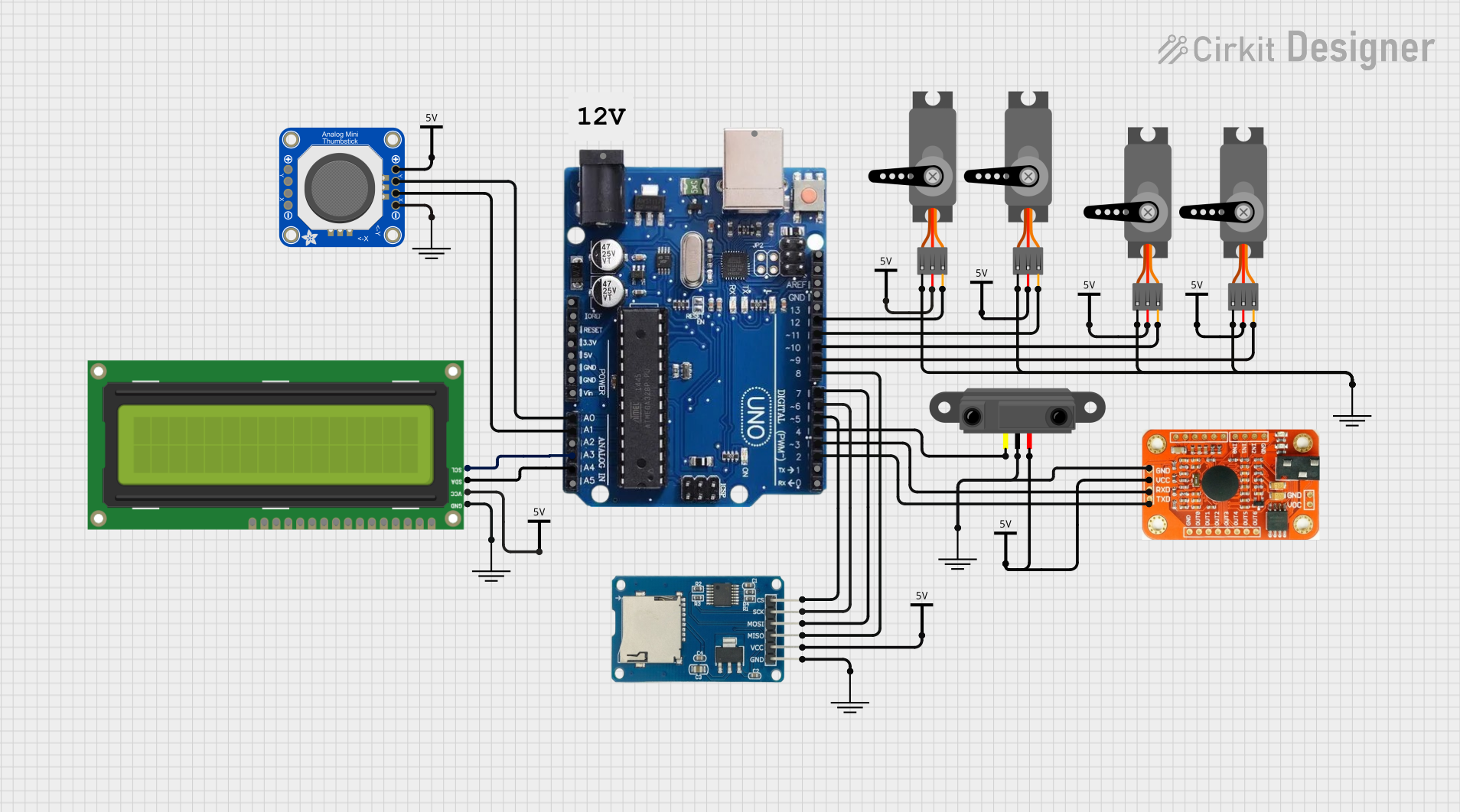

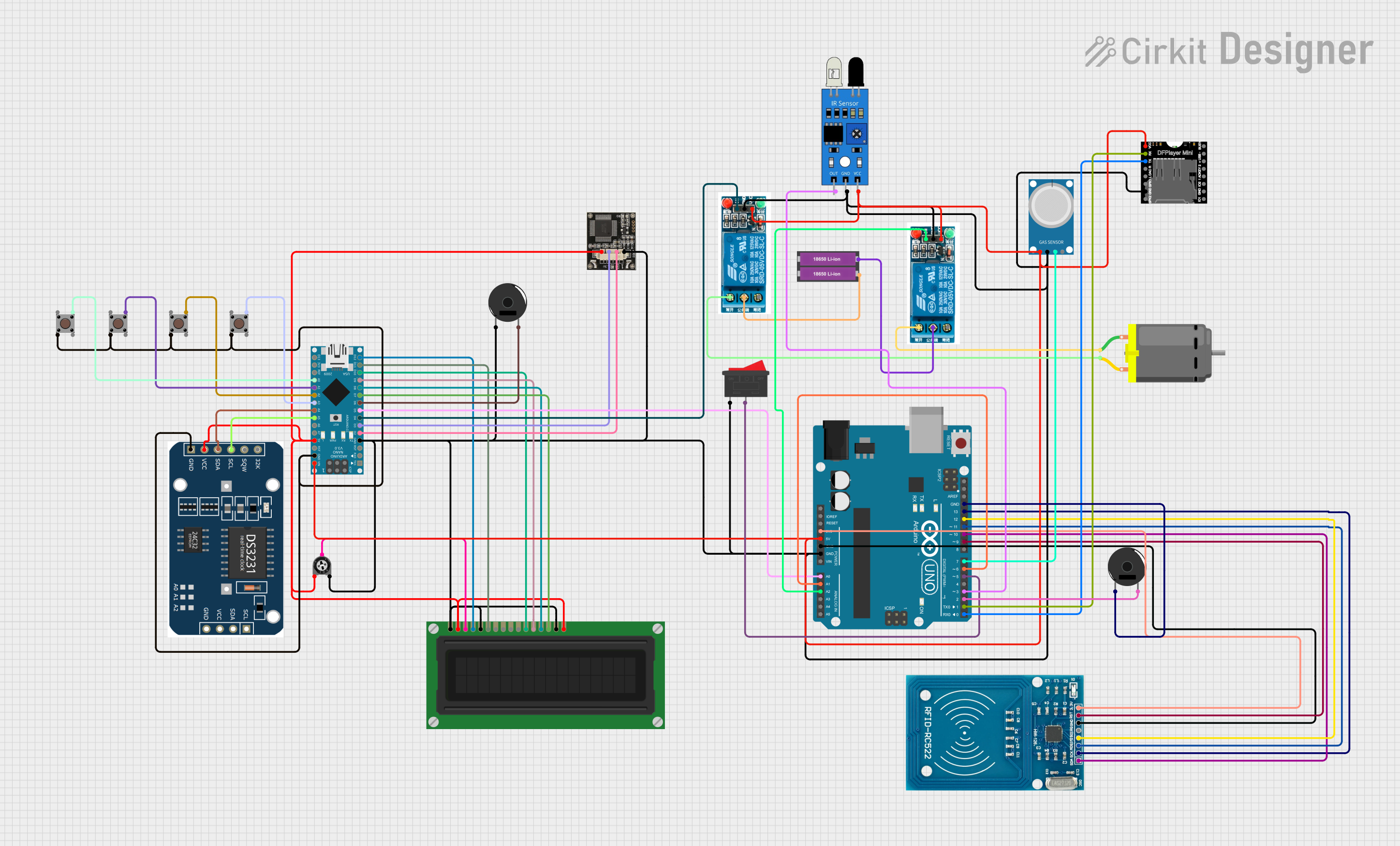
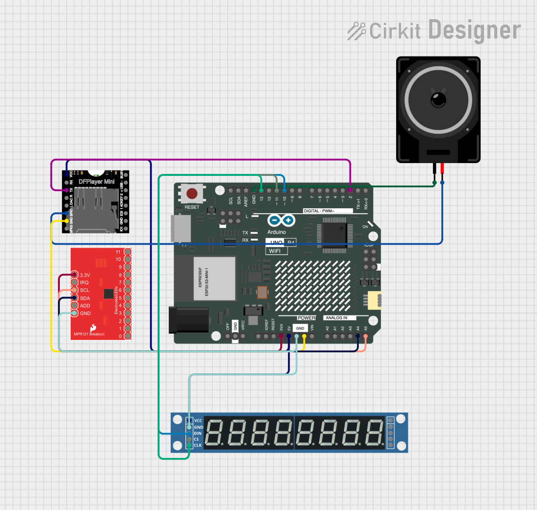
Explore Projects Built with UNO R4 MINI PRO
Common Applications and Use Cases
- Prototyping and development of IoT devices
- Robotics and automation systems
- Sensor data acquisition and processing
- Educational projects and STEM learning
- Home automation and DIY electronics
Technical Specifications
The following table outlines the key technical details of the UNO R4 MINI PRO:
| Parameter | Specification |
|---|---|
| Microcontroller | ATmega328P |
| Operating Voltage | 5V |
| Input Voltage (recommended) | 7-12V |
| Input Voltage (limit) | 6-20V |
| Digital I/O Pins | 14 (6 PWM outputs) |
| Analog Input Pins | 6 |
| DC Current per I/O Pin | 20 mA |
| Flash Memory | 32 KB (0.5 KB used by bootloader) |
| SRAM | 2 KB |
| EEPROM | 1 KB |
| Clock Speed | 16 MHz |
| USB Connectivity | Micro-USB |
| Dimensions | 68.6 mm x 53.4 mm |
| Weight | 25 g |
Pin Configuration and Descriptions
The pinout of the UNO R4 MINI PRO is as follows:
Digital Pins
| Pin Number | Function | Description |
|---|---|---|
| D0 - D1 | RX, TX | Serial communication pins |
| D2 - D13 | Digital I/O | General-purpose digital input/output pins |
| D3, D5, D6, D9, D10, D11 | PWM Output | Pulse Width Modulation capable pins |
Analog Pins
| Pin Number | Function | Description |
|---|---|---|
| A0 - A5 | Analog Input | Read analog signals (0-5V) |
Power Pins
| Pin Name | Function | Description |
|---|---|---|
| VIN | Input Voltage | External power supply input (7-12V recommended) |
| 5V | Regulated Power Out | Provides 5V output for external components |
| 3.3V | Regulated Power Out | Provides 3.3V output for external components |
| GND | Ground | Common ground for the circuit |
Usage Instructions
How to Use the UNO R4 MINI PRO in a Circuit
Powering the Board:
- Connect the board to your computer using a Micro-USB cable for programming and power.
- Alternatively, supply power through the VIN pin (7-12V recommended) or a DC barrel jack.
Connecting Components:
- Use the digital pins (D2-D13) for digital input/output operations.
- Connect sensors or other analog devices to the analog pins (A0-A5).
- Ensure that the current drawn by connected components does not exceed 20 mA per pin.
Programming the Board:
- Install the Arduino IDE on your computer.
- Select "Arduino UNO" as the board type in the IDE.
- Write your code, compile it, and upload it to the board via the USB connection.
Important Considerations and Best Practices
- Avoid exceeding the maximum voltage and current ratings of the pins to prevent damage.
- Use external pull-up or pull-down resistors for stable digital input signals.
- When connecting motors or high-power devices, use a separate power supply and appropriate driver circuits.
- Always double-check your wiring before powering the board to avoid short circuits.
Example Code for Arduino UNO R4 MINI PRO
The following example demonstrates how to blink an LED connected to pin 13:
// Blink an LED connected to digital pin 13
// This code toggles the LED on and off every second

void setup() {
  pinMode(13, OUTPUT); // Set pin 13 as an output
}

void loop() {
  digitalWrite(13, HIGH); // Turn the LED on
  delay(1000);            // Wait for 1 second
  digitalWrite(13, LOW);  // Turn the LED off
  delay(1000);            // Wait for 1 second
}
Troubleshooting and FAQs
Common Issues and Solutions
The board is not recognized by the computer:
- Ensure the USB cable is properly connected and functional.
- Install the necessary drivers for the Arduino UNO R4 MINI PRO.
- Check that the correct COM port is selected in the Arduino IDE.
Code upload fails:
- Verify that "Arduino UNO" is selected as the board type in the IDE.
- Ensure no other application is using the COM port.
- Press the reset button on the board before uploading the code.
Components connected to the board are not working:
- Double-check the wiring and connections.
- Ensure the components are compatible with the board's voltage and current ratings.
- Test the components individually to confirm they are functional.
FAQs
Q: Can I power the board with a 9V battery?
A: Yes, you can connect a 9V battery to the VIN pin or the DC barrel jack. Ensure the battery voltage does not exceed 12V for optimal performance.
Q: Is the UNO R4 MINI PRO compatible with Arduino shields?
A: Yes, the board is compatible with most Arduino UNO shields, provided they do not exceed the board's power and pin limitations.
Q: How do I reset the board?
A: Press the reset button located on the board to restart the microcontroller and reload the program.
By following this documentation, you can effectively utilize the UNO R4 MINI PRO in your projects and troubleshoot common issues with ease.