How to Use Seeed Studio nRF52840: Examples, Pinouts, and Specs
Introduction
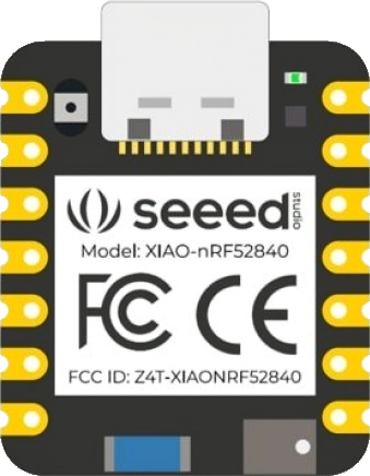
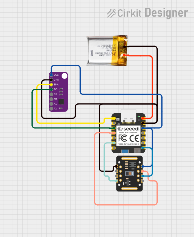
The Seeed Studio XIAO nRF52840 is a compact and powerful development board based on the Nordic Semiconductor nRF52840 SoC (System on Chip). This board is designed for wearable devices, IoT applications, and low-power projects. It features Bluetooth 5.0, NFC, and a built-in USB interface for programming and power supply.
Explore Projects Built with Seeed Studio nRF52840
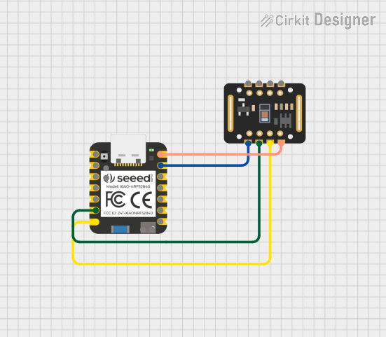
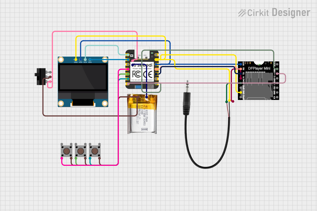
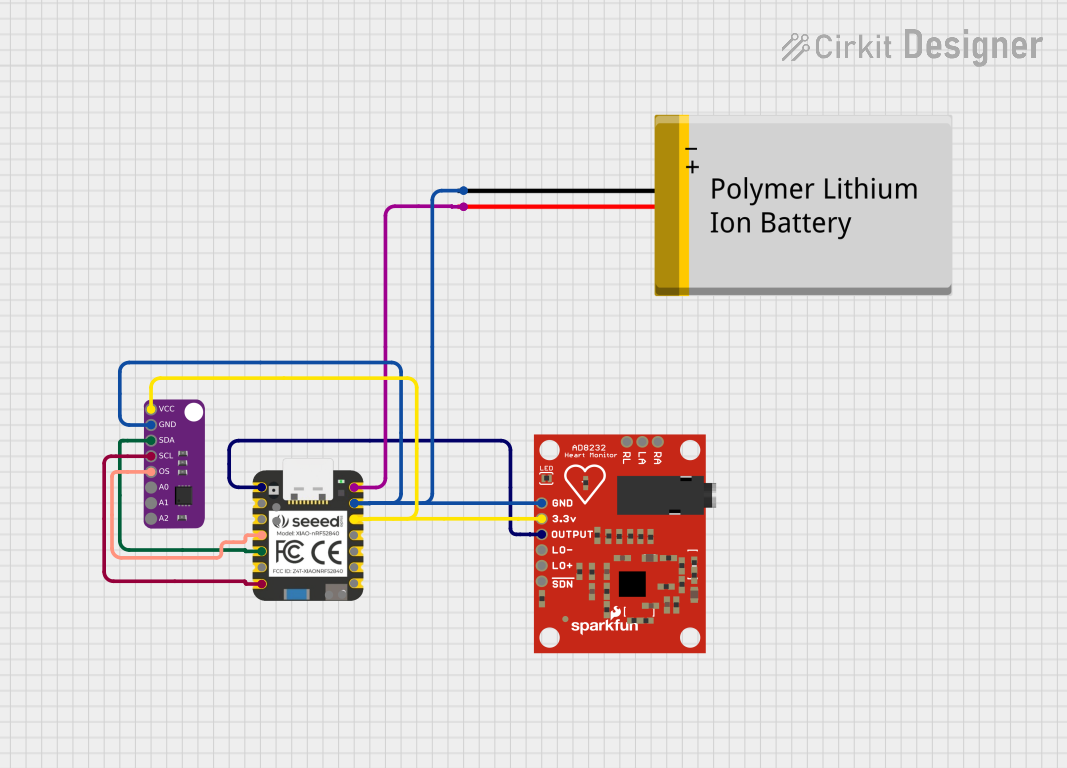
Explore Projects Built with Seeed Studio nRF52840
Common Applications and Use Cases
- Wearable devices
- Wireless sensor networks
- IoT applications
- Smart home devices
- Prototyping for Bluetooth-enabled products
Technical Specifications
Key Technical Details
- Microcontroller: Nordic Semiconductor nRF52840 SoC
- Operating Voltage: 3.3V
- Input Voltage (recommended): 5V via USB or 3.5-6V via battery
- Digital I/O Pins: 11, all can be used as PWM, I2C, or SPI
- Analog Input Pins: 4, 12-bit ADC channels
- Flash Memory: 1MB
- SRAM: 256KB
- Clock Speed: 64MHz
- Interfaces: I2C, SPI, UART, PWM, NFC, USB
- Bluetooth Version: 5.0
- Dimensions: 21mm x 17.5mm
Pin Configuration and Descriptions
| Pin Number | Function | Description |
|---|---|---|
| 1 | AREF | Analog reference voltage for ADC |
| 2 | GND | Ground |
| 3 | D0/TX | Digital I/O, UART Transmit |
| 4 | D1/RX | Digital I/O, UART Receive |
| 5 | D2 | Digital I/O, also SDA for I2C |
| 6 | D3 | Digital I/O, also SCL for I2C |
| 7 | D4 | Digital I/O, also MISO for SPI |
| 8 | D5 | Digital I/O, also MOSI for SPI |
| 9 | D6 | Digital I/O, also SCK for SPI |
| 10 | D7 | Digital I/O, also used for NFC as NFC1 |
| 11 | D8 | Digital I/O, also used for NFC as NFC2 |
| 12 | D9/A0 | Digital I/O, Analog Input |
| 13 | D10/A1 | Digital I/O, Analog Input |
| 14 | D11/A2 | Digital I/O, Analog Input |
| 15 | D12/A3 | Digital I/O, Analog Input |
| 16 | 3V3 | 3.3V power supply output |
| 17 | RESET | Reset pin (active low) |
| 18 | VBUS | USB power input |
| 19 | P0.26 | Digital I/O, can be used for custom functions |
| 20 | P1.11 | Digital I/O, can be used for custom functions |
Usage Instructions
How to Use the Component in a Circuit
Powering the Board:
- Connect the board to a computer or USB power source via the USB port for power.
- Alternatively, connect a battery to the designated battery input pins.
Programming:
- Use the USB interface to program the board with the Arduino IDE or other compatible development environments.
- Select the appropriate board and port in your development environment.
Connecting I/O:
- Connect sensors, actuators, or other peripherals to the digital and analog pins as required by your project.
- Ensure that the connected devices are compatible with the operating voltage of the board.
Important Considerations and Best Practices
- Voltage Levels: Do not exceed the recommended voltage levels on any I/O pin as this may damage the board.
- Current Draw: Be mindful of the total current draw from the board to avoid overloading the power source.
- Antenna Design: If designing custom RF applications, pay careful attention to antenna design to ensure optimal performance.
- Firmware Updates: Keep the board's firmware updated to the latest version for improved performance and security.
Troubleshooting and FAQs
Common Issues Users Might Face
Board Not Recognized by Computer:
- Ensure the USB cable is properly connected and functioning.
- Check that the correct drivers are installed on your computer.
Failure to Upload Sketch:
- Verify that the correct board and port are selected in the development environment.
- Press the reset button on the board and try uploading again.
Bluetooth Connectivity Issues:
- Ensure that the antenna design is correct and that there are no obstructions.
- Check that the Bluetooth device you are trying to connect to is compatible and within range.
Solutions and Tips for Troubleshooting
Driver Installation:
- If the board is not recognized, install the necessary drivers from the Seeed Studio website or use the board manager in the Arduino IDE.
Resetting the Board:
- If the board is unresponsive, use the reset button to restart it.
Updating Firmware:
- Regularly check for firmware updates and follow the manufacturer's instructions to update the board.
Consult Documentation:
- Refer to the Seeed Studio XIAO nRF52840's official documentation for detailed information and support.
FAQs
Q: Can I use the Arduino IDE to program the XIAO nRF52840?
- A: Yes, the Arduino IDE can be used to program the board after installing the appropriate board package.
Q: What is the maximum Bluetooth range of the board?
- A: The Bluetooth range can vary but typically is up to 100 meters in open space with a clear line of sight and proper antenna design.
Q: Can the board be powered by a battery?
- A: Yes, the board can be powered by a battery connected to the designated battery input pins.
For more detailed information and resources, visit the Seeed Studio website and the Nordic Semiconductor documentation for the nRF52840 SoC.