Cirkit Designer
Your all-in-one circuit design IDE
Home /
Component Documentation
How to Use Current Tranformer: Examples, Pinouts, and Specs

Introduction
The PZEM PZCT-02 Current Transformer is a device designed to measure alternating current (AC) by producing a reduced current proportional to the current in its primary winding. This allows for safe monitoring and measurement of high AC currents without directly interfacing with the high voltage lines.
Explore Projects Built with Current Tranformer
Voltage Regulated Transformer Power Supply Circuit

This circuit appears to be a power supply circuit with a transformer connected to a 12V battery for voltage step-up or step-down. It includes a rectification stage with a 1N4007 diode, smoothing with an electrolytic capacitor, and regulation using a Zener diode. Additionally, there are inductors for filtering and a BT139 600 triac for controlling AC power, possibly for dimming or switching applications.
Transformer-Based AC Bulb Control Circuit with NPN Transistor and Potentiometer
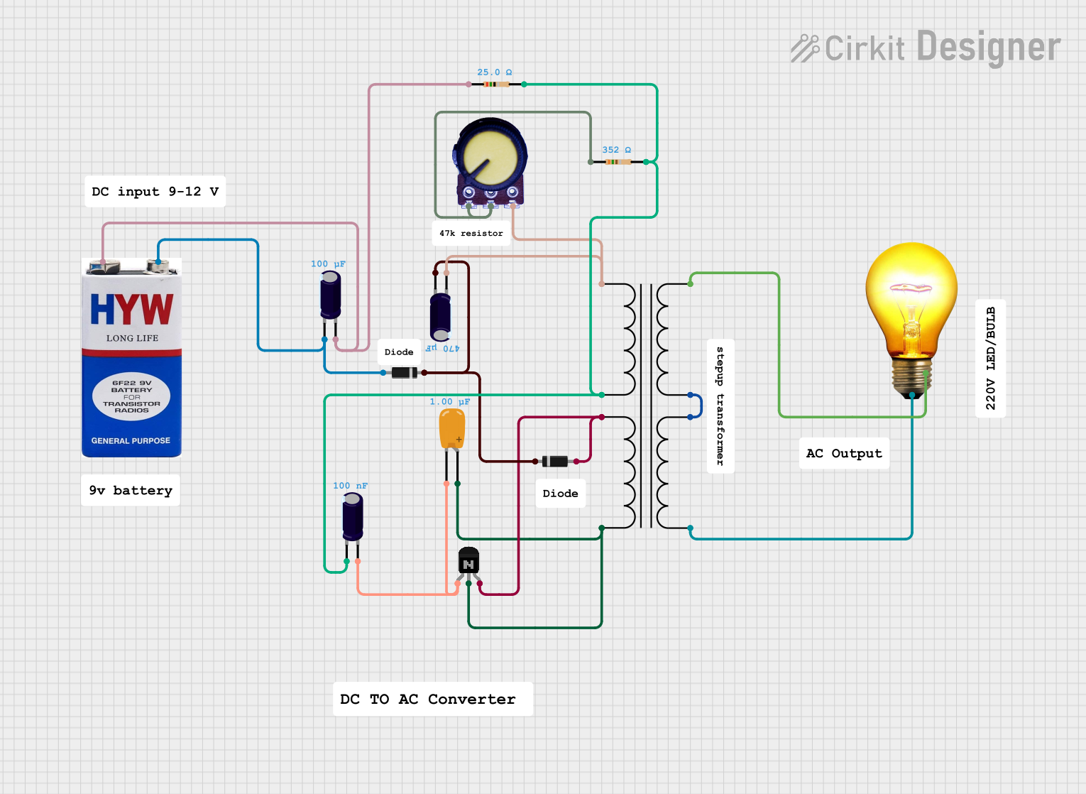
This circuit is a power supply and control system that includes a power transformer, various capacitors, diodes, resistors, a potentiometer, and an NPN transistor. It appears to regulate and rectify AC power to drive an AC bulb, with additional components for filtering and voltage control.
AC to DC Power Supply with Transformer and Bridge Rectifier

This circuit is a basic AC to DC power supply that steps down 220V AC to a lower voltage using a transformer, rectifies it to DC using a bridge rectifier made of diodes, and smooths the output with an electrolytic capacitor. A rocker switch is used to turn the power supply on and off.
TIP41C Transistor-Based Light Control Circuit with Transformer and Capacitor
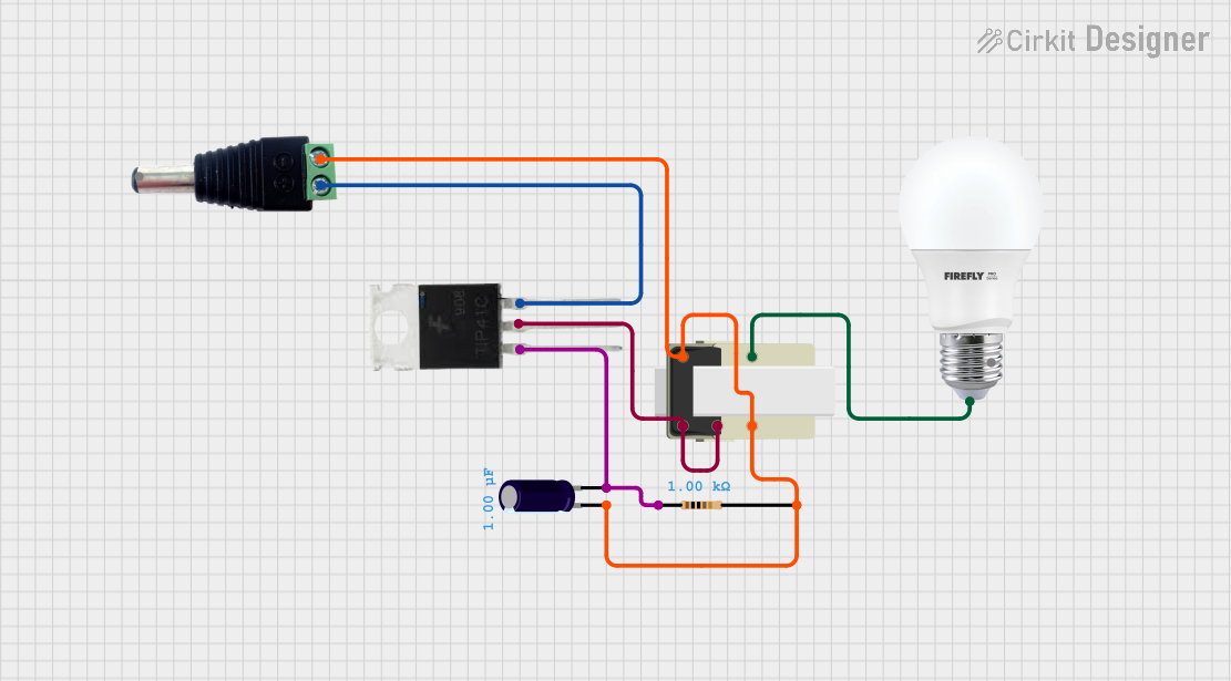
This circuit is a simple power supply and control system that uses a transformer to step down voltage, a TIP41C transistor for switching, and a capacitor for smoothing. The circuit powers a bulb, with a resistor and capacitor providing stabilization and control.
Explore Projects Built with Current Tranformer
Voltage Regulated Transformer Power Supply Circuit
This circuit appears to be a power supply circuit with a transformer connected to a 12V battery for voltage step-up or step-down. It includes a rectification stage with a 1N4007 diode, smoothing with an electrolytic capacitor, and regulation using a Zener diode. Additionally, there are inductors for filtering and a BT139 600 triac for controlling AC power, possibly for dimming or switching applications.
Transformer-Based AC Bulb Control Circuit with NPN Transistor and Potentiometer
This circuit is a power supply and control system that includes a power transformer, various capacitors, diodes, resistors, a potentiometer, and an NPN transistor. It appears to regulate and rectify AC power to drive an AC bulb, with additional components for filtering and voltage control.
AC to DC Power Supply with Transformer and Bridge Rectifier
This circuit is a basic AC to DC power supply that steps down 220V AC to a lower voltage using a transformer, rectifies it to DC using a bridge rectifier made of diodes, and smooths the output with an electrolytic capacitor. A rocker switch is used to turn the power supply on and off.
TIP41C Transistor-Based Light Control Circuit with Transformer and Capacitor
This circuit is a simple power supply and control system that uses a transformer to step down voltage, a TIP41C transistor for switching, and a capacitor for smoothing. The circuit powers a bulb, with a resistor and capacitor providing stabilization and control.
Common Applications and Use Cases
- Energy Monitoring Systems: Used in residential, commercial, and industrial settings to monitor energy consumption.
- Power Quality Analysis: Helps in analyzing the quality of power in electrical systems.
- Overcurrent Protection: Used in protective relays to detect overcurrent conditions.
- Smart Grids: Integral part of smart grid systems for real-time monitoring and control.
Technical Specifications
Key Technical Details
| Parameter | Value |
|---|---|
| Manufacturer | PZEM |
| Part ID | PZCT-02 |
| Rated Input Current | 0-100A AC |
| Output Current | 0-50mA AC |
| Accuracy Class | 0.5 |
| Operating Voltage | 660V AC |
| Frequency Range | 50-60Hz |
| Operating Temperature | -25°C to +70°C |
| Insulation Resistance | ≥100MΩ |
| Dielectric Strength | 3kV AC/1min |
Pin Configuration and Descriptions
| Pin Number | Pin Name | Description |
|---|---|---|
| 1 | S1 | Secondary winding terminal 1 |
| 2 | S2 | Secondary winding terminal 2 |
Usage Instructions
How to Use the PZCT-02 in a Circuit
- Primary Winding Connection: Pass the conductor carrying the AC current to be measured through the central hole of the current transformer.
- Secondary Winding Connection: Connect the secondary winding terminals (S1 and S2) to the measurement device (e.g., a microcontroller or an analog meter).
- Load Resistor: A load resistor is typically connected across the secondary winding to convert the current output to a voltage signal that can be easily measured.
Important Considerations and Best Practices
- Safety First: Always ensure the primary conductor is de-energized before installation.
- Proper Sizing: Ensure the current transformer is rated for the maximum current expected in the primary conductor.
- Calibration: Periodically calibrate the current transformer to maintain accuracy.
- Avoid Saturation: Do not exceed the rated current to avoid core saturation, which can lead to inaccurate measurements.
Example: Connecting to an Arduino UNO
To measure the current using an Arduino UNO, you can use the following setup and code:
Circuit Diagram
- Pass the AC wire through the PZCT-02.
- Connect S1 and S2 to a burden resistor (e.g., 100Ω).
- Connect the burden resistor to an analog input pin on the Arduino (e.g., A0).
Arduino Code
const int sensorPin = A0; // Pin connected to the burden resistor
const float burdenResistor = 100.0; // Burden resistor value in ohms
const float calibrationFactor = 0.05; // Calibration factor for the CT

void setup() {
  Serial.begin(9600); // Initialize serial communication
}

void loop() {
  int sensorValue = analogRead(sensorPin); // Read the analog input
  float voltage = sensorValue * (5.0 / 1023.0); // Convert to voltage
  float current = voltage / burdenResistor; // Calculate current
  current = current / calibrationFactor; // Apply calibration factor

  Serial.print("Current: ");
  Serial.print(current);
  Serial.println(" A");

  delay(1000); // Wait for 1 second before next reading
}
Troubleshooting and FAQs
Common Issues Users Might Face
- Inaccurate Readings:
- Solution: Ensure the burden resistor value is correct and the calibration factor is properly set.
- No Output Signal:
- Solution: Check the connections and ensure the primary conductor is carrying current.
- Overheating:
- Solution: Verify that the current transformer is not exceeding its rated current.
Solutions and Tips for Troubleshooting
- Check Connections: Ensure all connections are secure and correct.
- Verify Calibration: Periodically check and recalibrate the current transformer.
- Inspect for Damage: Regularly inspect the current transformer for any signs of physical damage.
By following this documentation, users can effectively utilize the PZEM PZCT-02 Current Transformer for accurate and safe AC current measurement in various applications.