How to Use Adjustable Voltage Output Buck Converter Multi-Channel Switching Power Supply Module: Examples, Pinouts, and Specs
Introduction
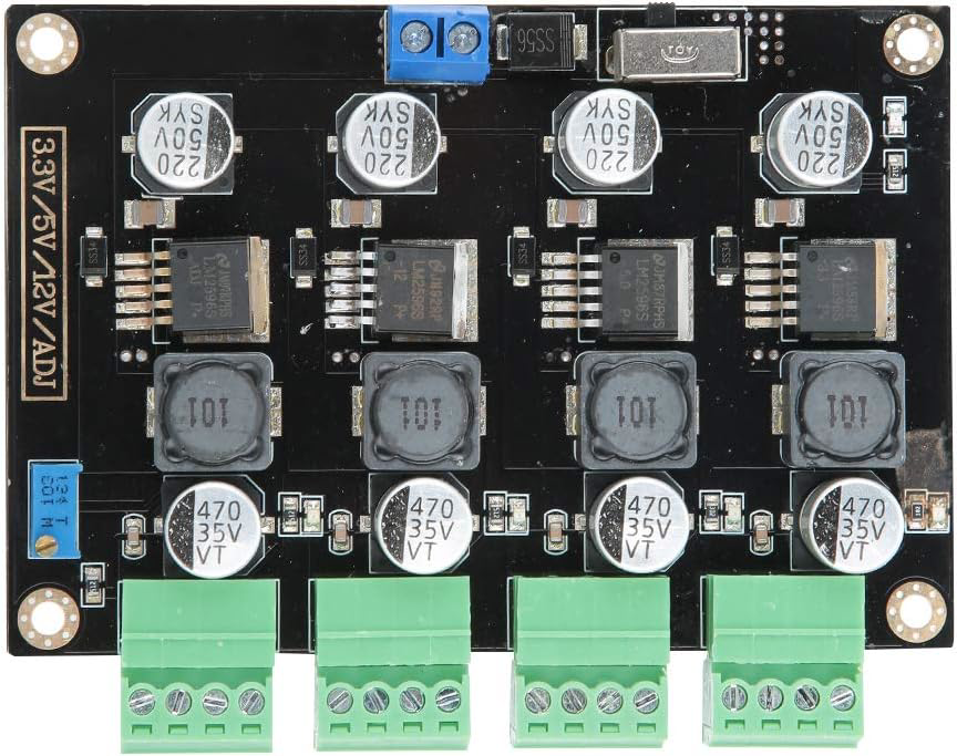
The Adjustable Voltage Output Buck Converter Multi-Channel Switching Power Supply Module by Estink is a versatile and efficient power supply module designed to step down a higher input voltage to a lower, adjustable output voltage. This module supports multiple output channels, making it ideal for powering various devices and circuits simultaneously. Its compact design and high efficiency make it suitable for a wide range of applications, including DIY electronics projects, embedded systems, robotics, and industrial automation.
Explore Projects Built with Adjustable Voltage Output Buck Converter Multi-Channel Switching Power Supply Module


Explore Projects Built with Adjustable Voltage Output Buck Converter Multi-Channel Switching Power Supply Module
Common Applications and Use Cases
- Powering microcontrollers (e.g., Arduino, Raspberry Pi) and sensors
- Supplying power to LED strips and displays
- Battery-powered systems requiring regulated voltage
- Multi-channel power distribution in embedded systems
- Prototyping and testing circuits with different voltage requirements
Technical Specifications
Below are the key technical details of the Estink Adjustable Voltage Output Buck Converter:
| Parameter | Specification |
|---|---|
| Input Voltage Range | 6V to 40V DC |
| Output Voltage Range | 1.25V to 36V DC (adjustable) |
| Output Channels | 2 or more (varies by model) |
| Maximum Output Current | 3A per channel (with proper heat dissipation) |
| Efficiency | Up to 92% |
| Switching Frequency | 150 kHz |
| Operating Temperature | -40°C to +85°C |
| Dimensions | 60mm x 40mm x 20mm |
Pin Configuration and Descriptions
The module typically features the following input and output connections:
| Pin/Terminal | Label | Description |
|---|---|---|
| VIN+ | Input + | Positive input voltage terminal (6V to 40V DC) |
| VIN- | Input - | Negative input voltage terminal (ground) |
| VOUT1+ | Output 1+ | Positive output voltage terminal for Channel 1 |
| VOUT1- | Output 1- | Negative output voltage terminal for Channel 1 |
| VOUT2+ | Output 2+ | Positive output voltage terminal for Channel 2 |
| VOUT2- | Output 2- | Negative output voltage terminal for Channel 2 |
| ADJ | Adjust | Potentiometer to adjust output voltage |
Usage Instructions
How to Use the Module in a Circuit
Connect the Input Voltage:
- Connect the positive terminal of your power source to the
VIN+pin. - Connect the negative terminal of your power source to the
VIN-pin. - Ensure the input voltage is within the specified range (6V to 40V DC).
- Connect the positive terminal of your power source to the
Adjust the Output Voltage:
- Use the onboard potentiometer labeled
ADJto set the desired output voltage. - Turn the potentiometer clockwise to increase the voltage and counterclockwise to decrease it.
- Use a multimeter to measure the output voltage at the
VOUT+andVOUT-terminals for precise adjustment.
- Use the onboard potentiometer labeled
Connect the Load:
- Connect your load (e.g., microcontroller, LED strip) to the appropriate output channel (
VOUT1+/VOUT1-orVOUT2+/VOUT2-). - Ensure the load does not exceed the maximum current rating of 3A per channel.
- Connect your load (e.g., microcontroller, LED strip) to the appropriate output channel (
Power On:
- Turn on the power source and verify the output voltage and current using a multimeter.
Important Considerations and Best Practices
- Heat Dissipation: If the module operates at high currents (close to 3A), ensure proper heat dissipation by attaching a heatsink or providing adequate airflow.
- Input Voltage: Always ensure the input voltage is higher than the desired output voltage by at least 1.5V for stable operation.
- Short Circuit Protection: While the module may have basic protection, avoid shorting the output terminals to prevent damage.
- Multi-Channel Usage: When using multiple channels, ensure the total current draw does not exceed the module's thermal limits.
Example: Using with an Arduino UNO
To power an Arduino UNO with a 5V regulated output from the module:
- Set the input voltage to 12V DC.
- Adjust the output voltage to 5V using the potentiometer.
- Connect the
VOUT1+terminal to the Arduino's5Vpin and theVOUT1-terminal to theGNDpin.
Here is a simple Arduino code to blink an LED, powered by the module:
// Blink an LED connected to pin 13
void setup() {
  pinMode(13, OUTPUT); // Set pin 13 as an output
}

void loop() {
  digitalWrite(13, HIGH); // Turn the LED on
  delay(1000);            // Wait for 1 second
  digitalWrite(13, LOW);  // Turn the LED off
  delay(1000);            // Wait for 1 second
}
Troubleshooting and FAQs
Common Issues and Solutions
No Output Voltage:
- Cause: Input voltage is not connected or is below the minimum required level.
- Solution: Verify the input voltage is within the 6V to 40V range and properly connected.
Output Voltage is Unstable:
- Cause: Load current exceeds the module's capacity or input voltage is insufficient.
- Solution: Reduce the load current or increase the input voltage.
Module Overheats:
- Cause: High current draw without proper heat dissipation.
- Solution: Attach a heatsink or improve airflow around the module.
Cannot Adjust Output Voltage:
- Cause: Potentiometer is damaged or incorrectly adjusted.
- Solution: Check the potentiometer for damage and adjust it carefully.
FAQs
Q: Can I use this module to charge a battery?
A: Yes, but ensure the output voltage is set to the appropriate charging voltage for the battery type, and use a current-limiting circuit if necessary.
Q: Can I use both output channels simultaneously?
A: Yes, but ensure the total current draw does not exceed the module's thermal and electrical limits.
Q: Is the module protected against reverse polarity?
A: No, the module does not have built-in reverse polarity protection. Always double-check your connections before powering on.
Q: Can I use this module with an AC power source?
A: No, the module requires a DC input voltage. Use an AC-to-DC adapter if necessary.
This concludes the documentation for the Adjustable Voltage Output Buck Converter Multi-Channel Switching Power Supply Module by Estink.