Cirkit Designer
Your all-in-one circuit design IDE
Home /
Component Documentation
How to Use tower lamp: Examples, Pinouts, and Specs
Introduction
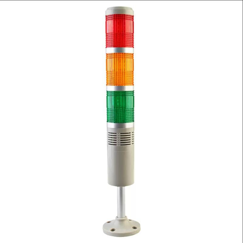
A tower lamp, also known as a signal tower or stack light, is an essential indicator light used in industrial settings to signal the status of a machine or process. It typically consists of multiple colored lights stacked vertically, each representing a different status or condition. These lights can be red, yellow, green, blue, or white, and they provide a clear visual indication of the operational state, warnings, or errors in machinery and processes.
Explore Projects Built with tower lamp
USB-Powered Light Sensor with Pilot Lamp Indicator
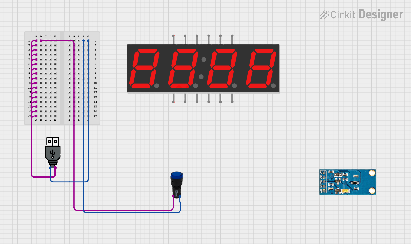
This circuit powers a blue pilot lamp using a USB power source. The positive terminal of the USB power is connected to one pin of the pilot lamp, while the negative terminal is connected to the other pin, allowing the lamp to illuminate when the USB power is supplied.
Toggle Switch Controlled Lamp Circuit with Banana Sockets

This circuit consists of two toggle switches and a red lamp connected to panel mount banana sockets. The switches control the connection between the red and black banana sockets, allowing the lamp to be turned on or off depending on the switch positions.
LDR-Activated Relay Control for Dual Bulb Illumination

This circuit appears to be a light-activated switch controlling two bulbs using a 5V relay, with an LDR (Light Dependent Resistor) as the sensor. The relay is powered by a 48V to 5V converter, which is switched on by a 12V battery through an SPST toggle switch. The LDR's output is connected to the relay's input, enabling the relay to switch the bulbs on or off based on the ambient light level detected by the LDR.
Arduino-Controlled Servo with Light Sensing
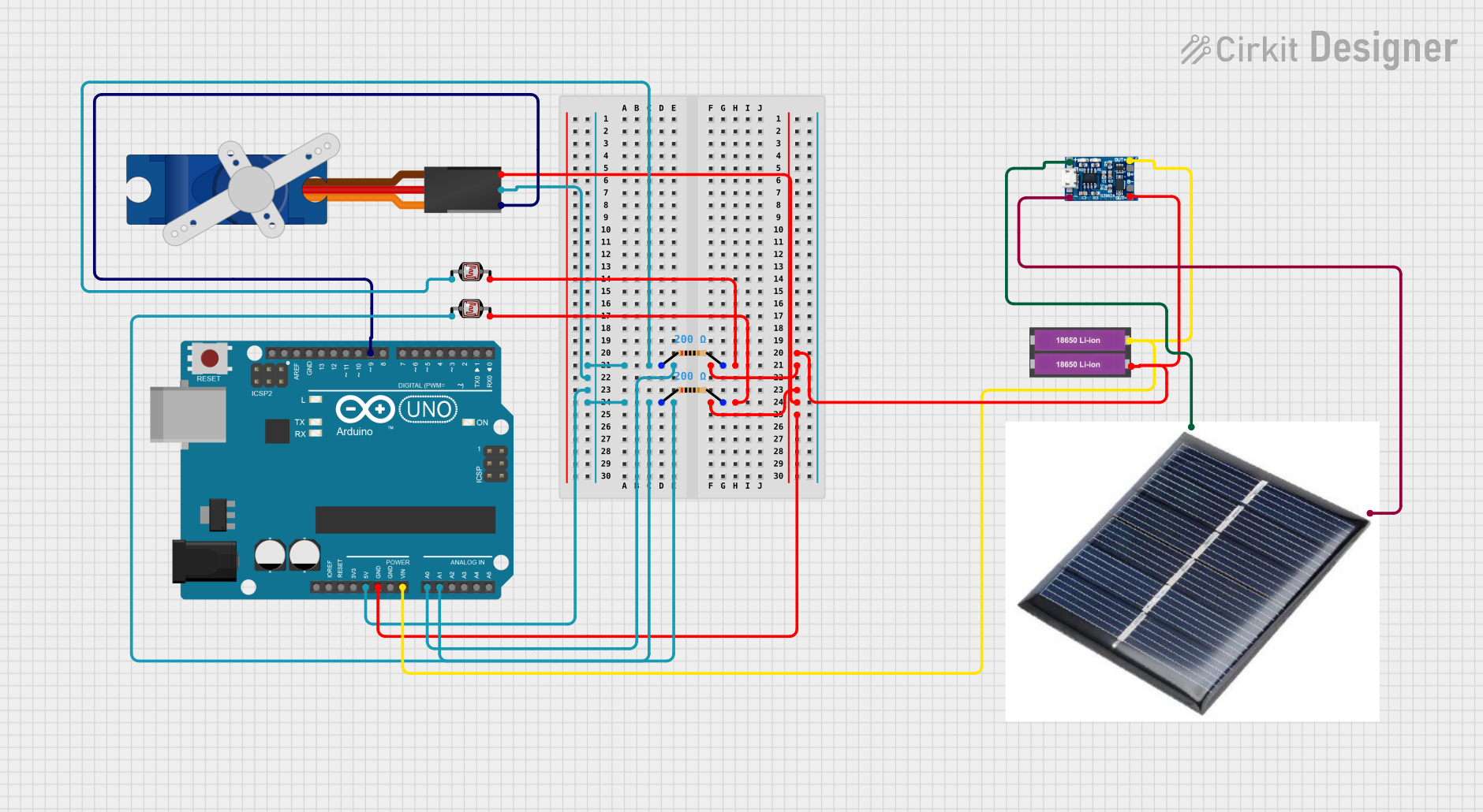
This circuit features an Arduino UNO microcontroller interfaced with two photocells (LDRs) and a servo motor. The photocells are connected to analog inputs A0 and A1, and their average light intensity reading is used to control the position of the servo motor connected to digital pin D9. The circuit is powered by a pair of 18650 Li-ion batteries, which are also connected to a TP4056 charging module that can be charged via a solar cell, providing a renewable energy source for the system.
Explore Projects Built with tower lamp
USB-Powered Light Sensor with Pilot Lamp Indicator
This circuit powers a blue pilot lamp using a USB power source. The positive terminal of the USB power is connected to one pin of the pilot lamp, while the negative terminal is connected to the other pin, allowing the lamp to illuminate when the USB power is supplied.
Toggle Switch Controlled Lamp Circuit with Banana Sockets
This circuit consists of two toggle switches and a red lamp connected to panel mount banana sockets. The switches control the connection between the red and black banana sockets, allowing the lamp to be turned on or off depending on the switch positions.
LDR-Activated Relay Control for Dual Bulb Illumination
This circuit appears to be a light-activated switch controlling two bulbs using a 5V relay, with an LDR (Light Dependent Resistor) as the sensor. The relay is powered by a 48V to 5V converter, which is switched on by a 12V battery through an SPST toggle switch. The LDR's output is connected to the relay's input, enabling the relay to switch the bulbs on or off based on the ambient light level detected by the LDR.
Arduino-Controlled Servo with Light Sensing
This circuit features an Arduino UNO microcontroller interfaced with two photocells (LDRs) and a servo motor. The photocells are connected to analog inputs A0 and A1, and their average light intensity reading is used to control the position of the servo motor connected to digital pin D9. The circuit is powered by a pair of 18650 Li-ion batteries, which are also connected to a TP4056 charging module that can be charged via a solar cell, providing a renewable energy source for the system.
Common Applications and Use Cases
- Manufacturing Plants: Indicating machine status (e.g., running, stopped, error).
- Assembly Lines: Signaling the need for operator intervention.
- Warehouses: Indicating the status of automated systems.
- Quality Control: Alerting operators to inspection results.
- Safety Systems: Providing visual alerts for hazardous conditions.
Technical Specifications
Key Technical Details
| Parameter | Value |
|---|---|
| Operating Voltage | 24V DC |
| Current Consumption | 20mA per light module |
| Power Rating | 0.48W per light module |
| Light Colors | Red, Yellow, Green, Blue, White |
| Mounting Type | Vertical, with base mount |
| Material | Polycarbonate (lens), ABS (housing) |
| IP Rating | IP54 |
Pin Configuration and Descriptions
| Pin Number | Color | Description |
|---|---|---|
| 1 | Red | Red light positive terminal |
| 2 | Yellow | Yellow light positive terminal |
| 3 | Green | Green light positive terminal |
| 4 | Blue | Blue light positive terminal |
| 5 | White | White light positive terminal |
| 6 | Black | Common ground |
Usage Instructions
How to Use the Component in a Circuit
- Power Supply: Ensure you have a 24V DC power supply to power the tower lamp.
- Wiring: Connect the common ground (black wire) to the ground of your power supply.
- Control Signals: Connect each colored light's positive terminal to the control signals from your microcontroller or PLC (Programmable Logic Controller).
Example Circuit with Arduino UNO
// Define pin connections
const int redPin = 2;
const int yellowPin = 3;
const int greenPin = 4;
const int bluePin = 5;
const int whitePin = 6;

void setup() {
  // Initialize pins as outputs
  pinMode(redPin, OUTPUT);
  pinMode(yellowPin, OUTPUT);
  pinMode(greenPin, OUTPUT);
  pinMode(bluePin, OUTPUT);
  pinMode(whitePin, OUTPUT);
}

void loop() {
  // Example sequence to turn on each light for 1 second
  digitalWrite(redPin, HIGH);  // Turn on red light
  delay(1000);                 // Wait for 1 second
  digitalWrite(redPin, LOW);   // Turn off red light

  digitalWrite(yellowPin, HIGH); // Turn on yellow light
  delay(1000);                   // Wait for 1 second
  digitalWrite(yellowPin, LOW);  // Turn off yellow light

  digitalWrite(greenPin, HIGH);  // Turn on green light
  delay(1000);                   // Wait for 1 second
  digitalWrite(greenPin, LOW);   // Turn off green light

  digitalWrite(bluePin, HIGH);   // Turn on blue light
  delay(1000);                   // Wait for 1 second
  digitalWrite(bluePin, LOW);    // Turn off blue light

  digitalWrite(whitePin, HIGH);  // Turn on white light
  delay(1000);                   // Wait for 1 second
  digitalWrite(whitePin, LOW);   // Turn off white light
}
Important Considerations and Best Practices
- Voltage Compatibility: Ensure the tower lamp's operating voltage matches your power supply.
- Current Limiting: Use appropriate current-limiting resistors if necessary to prevent overcurrent.
- Environmental Protection: Verify the IP rating to ensure suitability for your environment.
- Mounting: Securely mount the tower lamp to prevent vibrations or movement.
Troubleshooting and FAQs
Common Issues Users Might Face
Lights Not Turning On:
- Solution: Check the power supply and ensure it is providing 24V DC. Verify all connections are secure and correct.
Incorrect Light Sequence:
- Solution: Double-check the pin connections and ensure the control signals are correctly programmed.
Flickering Lights:
- Solution: Ensure a stable power supply. Check for loose connections or potential short circuits.
Solutions and Tips for Troubleshooting
- Multimeter Use: Utilize a multimeter to check voltage levels and continuity in the circuit.
- Code Debugging: If using a microcontroller, use serial print statements to debug the control logic.
- Component Testing: Test each light module individually to ensure they are functioning correctly.
By following this documentation, users can effectively integrate and utilize a tower lamp in their industrial applications, ensuring clear and reliable status indication.