How to Use SparkFun RGB Light Sensor - ISL29125: Examples, Pinouts, and Specs
Introduction
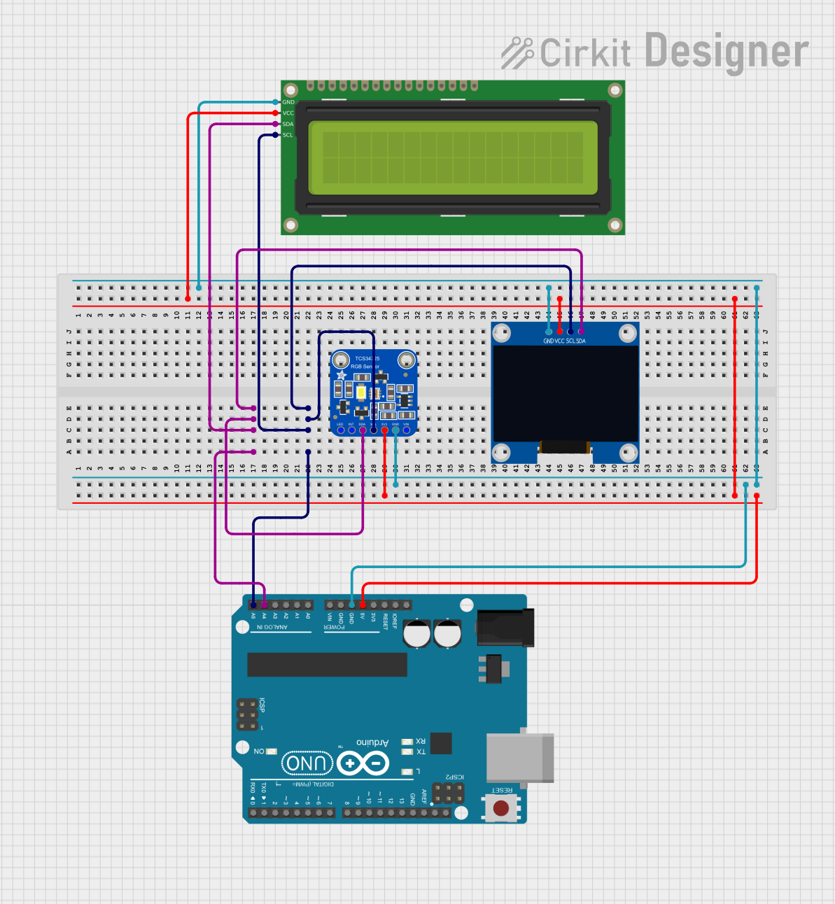
The SparkFun RGB Light Sensor - ISL29125 is a compact and versatile sensor designed to detect ambient light levels in red, green, and blue (RGB) wavelengths. This sensor enables accurate color detection and light intensity measurement, making it ideal for applications in robotics, automation, display calibration, and environmental monitoring. The ISL29125 communicates via the I2C protocol, ensuring seamless integration with microcontrollers and development boards like the Arduino UNO.
Explore Projects Built with SparkFun RGB Light Sensor - ISL29125
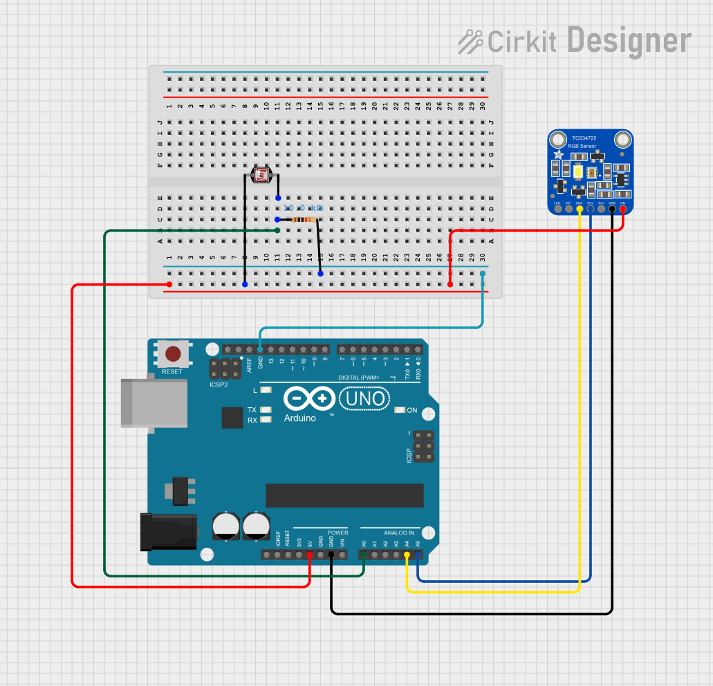
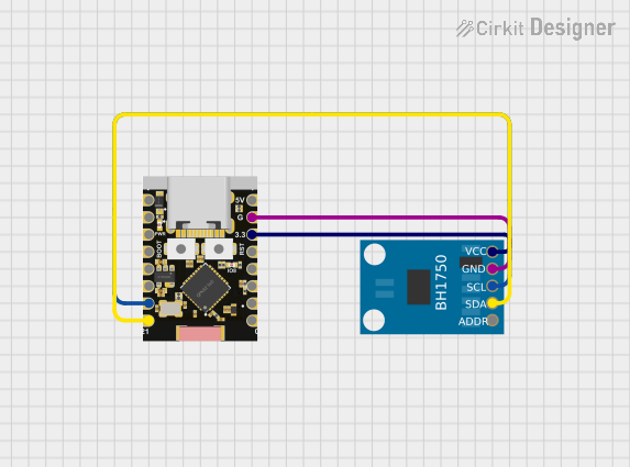
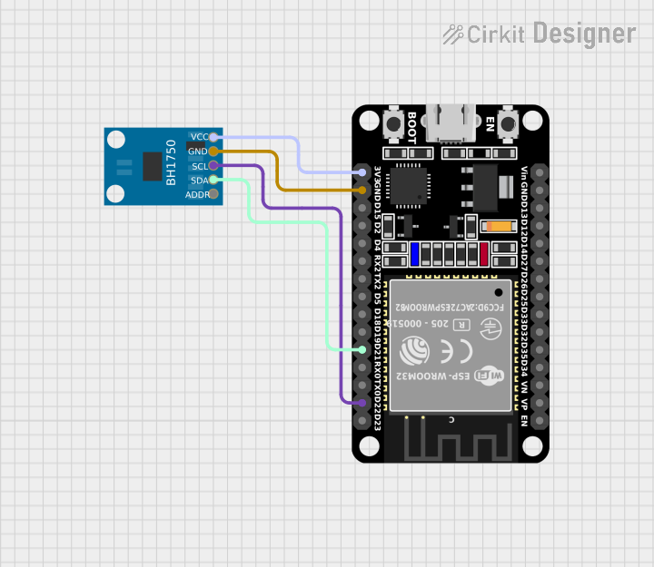
Explore Projects Built with SparkFun RGB Light Sensor - ISL29125
Technical Specifications
- Manufacturer: SparkFun
- Part ID: ISL29125
- Operating Voltage: 2.25V to 3.63V
- I2C Address: 0x44 (default, configurable)
- Current Consumption: 56 µA (typical in RGB mode)
- Measurement Range:
- Red, Green, Blue: 5.7m lux to 10,000 lux
- Communication Protocol: I2C
- Operating Temperature: -40°C to +85°C
- Package Type: QFN-10
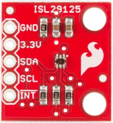
Pin Configuration and Descriptions
The ISL29125 sensor is typically mounted on a breakout board. Below is the pin configuration for the breakout board:
| Pin Name | Description |
|---|---|
| VCC | Power supply input (2.25V to 3.63V). Connect to 3.3V for most applications. |
| GND | Ground connection. |
| SDA | I2C data line. Connect to the microcontroller's SDA pin. |
| SCL | I2C clock line. Connect to the microcontroller's SCL pin. |
| INT | Interrupt pin. Can be used to signal when a measurement is ready (optional). |
Usage Instructions
How to Use the Component in a Circuit
- Power the Sensor:
Connect the VCC pin to a 3.3V power source and the GND pin to ground. - I2C Communication:
- Connect the SDA pin to the SDA pin of your microcontroller.
- Connect the SCL pin to the SCL pin of your microcontroller.
- Use 4.7kΩ pull-up resistors on the SDA and SCL lines if not already present.
- Optional Interrupt:
- Connect the INT pin to a GPIO pin on your microcontroller if you want to use the interrupt feature.
Important Considerations and Best Practices
- Voltage Levels: Ensure the microcontroller's I2C pins operate at 3.3V logic levels. If using a 5V microcontroller, use a level shifter.
- Ambient Light: Avoid placing the sensor in direct sunlight or near strong light sources to prevent saturation.
- I2C Address Conflicts: If multiple I2C devices are connected, ensure no address conflicts.
Example Code for Arduino UNO
Below is an example Arduino sketch to read RGB values from the ISL29125 sensor:
#include <Wire.h>
#include <SparkFun_ISL29125.h> // Include the ISL29125 library

// Create an ISL29125 object
SparkFun_ISL29125 rgbSensor;

void setup() {
  Serial.begin(9600); // Initialize serial communication
  Wire.begin();       // Initialize I2C communication

  // Initialize the ISL29125 sensor
  if (!rgbSensor.init()) {
    Serial.println("Sensor initialization failed!");
    while (1); // Halt execution if initialization fails
  }
  Serial.println("Sensor initialized successfully.");
}

void loop() {
  // Read RGB values from the sensor
  uint16_t red = rgbSensor.readRed();
  uint16_t green = rgbSensor.readGreen();
  uint16_t blue = rgbSensor.readBlue();

  // Print the RGB values to the Serial Monitor
  Serial.print("Red: ");
  Serial.print(red);
  Serial.print(" Green: ");
  Serial.print(green);
  Serial.print(" Blue: ");
  Serial.println(blue);

  delay(500); // Wait 500ms before the next reading
}
Notes on the Code
- Install the SparkFun ISL29125 Arduino Library from the Arduino Library Manager before running the code.
- Ensure the I2C pull-up resistors are in place for proper communication.
Troubleshooting and FAQs
Common Issues and Solutions
Sensor Not Detected on I2C Bus:
- Verify the wiring connections (SDA, SCL, VCC, GND).
- Check for address conflicts with other I2C devices.
- Use an I2C scanner sketch to confirm the sensor's address.
Incorrect or Saturated Readings:
- Ensure the sensor is not exposed to direct sunlight or overly bright light sources.
- Verify the power supply voltage is within the specified range (2.25V to 3.63V).
Interrupt Pin Not Working:
- Confirm the interrupt pin is properly connected to the microcontroller.
- Check the sensor's configuration to ensure interrupts are enabled.
FAQs
Can the ISL29125 measure light intensity in lux?
No, the sensor provides raw RGB values. You can calculate lux using additional algorithms if needed.What is the maximum I2C clock speed supported?
The ISL29125 supports I2C clock speeds up to 400kHz (Fast Mode).Can I use the ISL29125 with a 5V microcontroller?
Yes, but you must use a level shifter to convert the 5V I2C signals to 3.3V.
By following this documentation, you can effectively integrate the SparkFun RGB Light Sensor - ISL29125 into your projects for accurate color and light intensity measurements.