How to Use AHT25: Examples, Pinouts, and Specs
Introduction
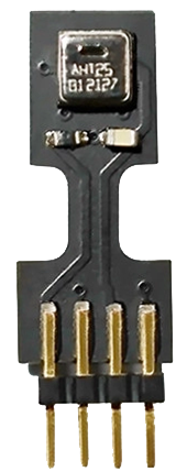
The AHT25 is a digital temperature and humidity sensor manufactured by ASAIR (AOSONG). It is designed to provide accurate and reliable measurements of environmental conditions, making it ideal for a wide range of applications. The sensor features a built-in I2C interface, which simplifies integration with microcontrollers and other digital systems. With its high precision, low power consumption, and compact design, the AHT25 is well-suited for use in consumer electronics, HVAC systems, weather monitoring, and industrial automation.
Explore Projects Built with AHT25
Explore Projects Built with AHT25
Common Applications
- Smart home devices (e.g., thermostats, air purifiers)
- Weather stations and environmental monitoring
- Industrial process control
- HVAC systems for temperature and humidity regulation
- IoT (Internet of Things) applications
Technical Specifications
The AHT25 sensor offers the following key technical specifications:
| Parameter | Value |
|---|---|
| Supply Voltage (VDD) | 2.0V to 5.5V |
| Typical Operating Voltage | 3.3V |
| Average Current Consumption | 0.25 mA (measuring) |
| Communication Interface | I2C |
| Temperature Range | -40°C to +85°C |
| Temperature Accuracy | ±0.3°C |
| Humidity Range | 0% to 100% RH |
| Humidity Accuracy | ±2% RH (20% to 80% RH) |
| Response Time | ≤8 seconds |
| Dimensions | 3.6mm x 2.4mm x 0.8mm |
Pin Configuration and Descriptions
The AHT25 has four pins, as described in the table below:
| Pin Name | Pin Number | Description |
|---|---|---|
| VDD | 1 | Power supply pin (2.0V to 5.5V) |
| GND | 2 | Ground pin |
| SDA | 3 | I2C data line |
| SCL | 4 | I2C clock line |
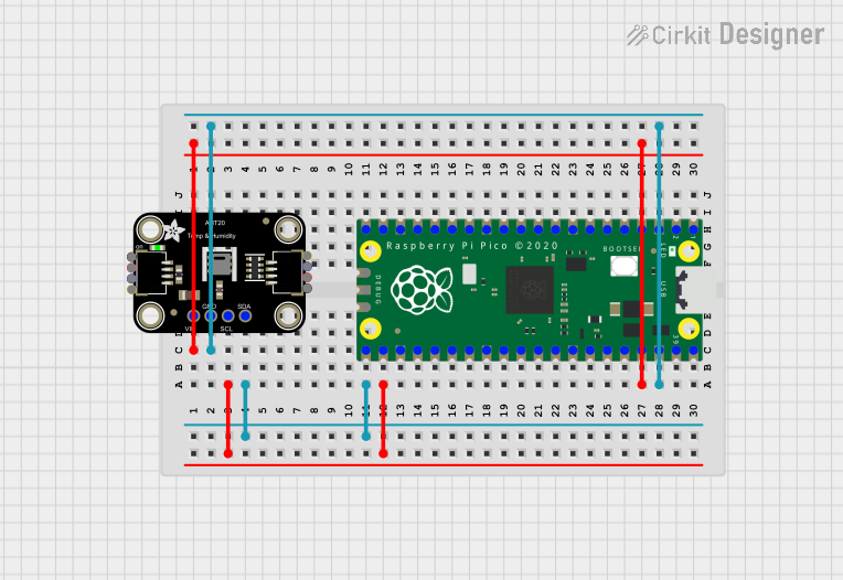
Usage Instructions
How to Use the AHT25 in a Circuit
- Power Supply: Connect the VDD pin to a 3.3V or 5V power source and the GND pin to ground.
- I2C Communication: Connect the SDA and SCL pins to the corresponding I2C pins on your microcontroller. Use pull-up resistors (typically 4.7kΩ) on both SDA and SCL lines if not already provided by your microcontroller.
- Initialization: Initialize the I2C interface on your microcontroller and configure the AHT25 for data acquisition.
- Data Reading: Send the appropriate I2C commands to read temperature and humidity data from the sensor.
Important Considerations
- Power Stability: Ensure a stable power supply to avoid measurement errors.
- Placement: Avoid placing the sensor in areas with high airflow or direct exposure to water droplets, as this may affect accuracy.
- I2C Address: The default I2C address of the AHT25 is
0x38. Ensure no address conflicts if multiple I2C devices are used. - Warm-Up Time: Allow the sensor to stabilize for at least 20ms after power-up before taking measurements.
Example Code for Arduino UNO
Below is an example of how to interface the AHT25 with an Arduino UNO using the I2C protocol:
#include <Wire.h>

// AHT25 I2C address
#define AHT25_ADDRESS 0x38

void setup() {
  Wire.begin(); // Initialize I2C communication
  Serial.begin(9600); // Initialize serial communication for debugging

  // Initialize the AHT25 sensor
  Wire.beginTransmission(AHT25_ADDRESS);
  Wire.write(0xE1); // Send initialization command
  Wire.endTransmission();
  delay(20); // Wait for sensor to stabilize
}

void loop() {
  // Request data from the AHT25 sensor
  Wire.beginTransmission(AHT25_ADDRESS);
  Wire.write(0xAC); // Trigger measurement command
  Wire.write(0x33); // Data byte 1
  Wire.write(0x00); // Data byte 2
  Wire.endTransmission();
  delay(80); // Wait for measurement to complete

  // Read 6 bytes of data from the sensor
  Wire.requestFrom(AHT25_ADDRESS, 6);
  if (Wire.available() == 6) {
    uint8_t data[6];
    for (int i = 0; i < 6; i++) {
      data[i] = Wire.read();
    }

    // Process temperature and humidity data
    uint32_t humidity = ((uint32_t)data[1] << 12) | ((uint32_t)data[2] << 4) | (data[3] >> 4);
    uint32_t temperature = ((uint32_t)(data[3] & 0x0F) << 16) | ((uint32_t)data[4] << 8) | data[5];

    float humidityPercent = (humidity * 100.0) / 1048576.0; // Convert to percentage
    float temperatureCelsius = (temperature * 200.0 / 1048576.0) - 50.0; // Convert to Celsius

    // Print results to the serial monitor
    Serial.print("Humidity: ");
    Serial.print(humidityPercent);
    Serial.println(" %");
    Serial.print("Temperature: ");
    Serial.print(temperatureCelsius);
    Serial.println(" °C");
  }

  delay(2000); // Wait 2 seconds before the next reading
}
Troubleshooting and FAQs
Common Issues
No Data from Sensor:
- Cause: Incorrect I2C wiring or address mismatch.
- Solution: Verify the SDA and SCL connections and ensure the I2C address is set to
0x38.
Inaccurate Readings:
- Cause: Sensor placement in an unstable environment (e.g., high airflow).
- Solution: Place the sensor in a stable environment and ensure proper ventilation.
Initialization Failure:
- Cause: Insufficient warm-up time or incorrect initialization sequence.
- Solution: Allow at least 20ms for the sensor to stabilize after power-up and verify the initialization commands.
FAQs
Q: Can the AHT25 operate at 5V?
- A: Yes, the AHT25 supports a supply voltage range of 2.0V to 5.5V.
Q: Do I need external pull-up resistors for I2C?
- A: Yes, if your microcontroller does not have built-in pull-up resistors, you need to add external ones (typically 4.7kΩ).
Q: How often can I take measurements?
- A: The AHT25 has a response time of ≤8 seconds, but for most applications, a 2-second interval is sufficient.
This concludes the documentation for the AHT25 sensor.