How to Use Pilot Lamp Green: Examples, Pinouts, and Specs
Introduction
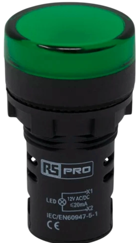
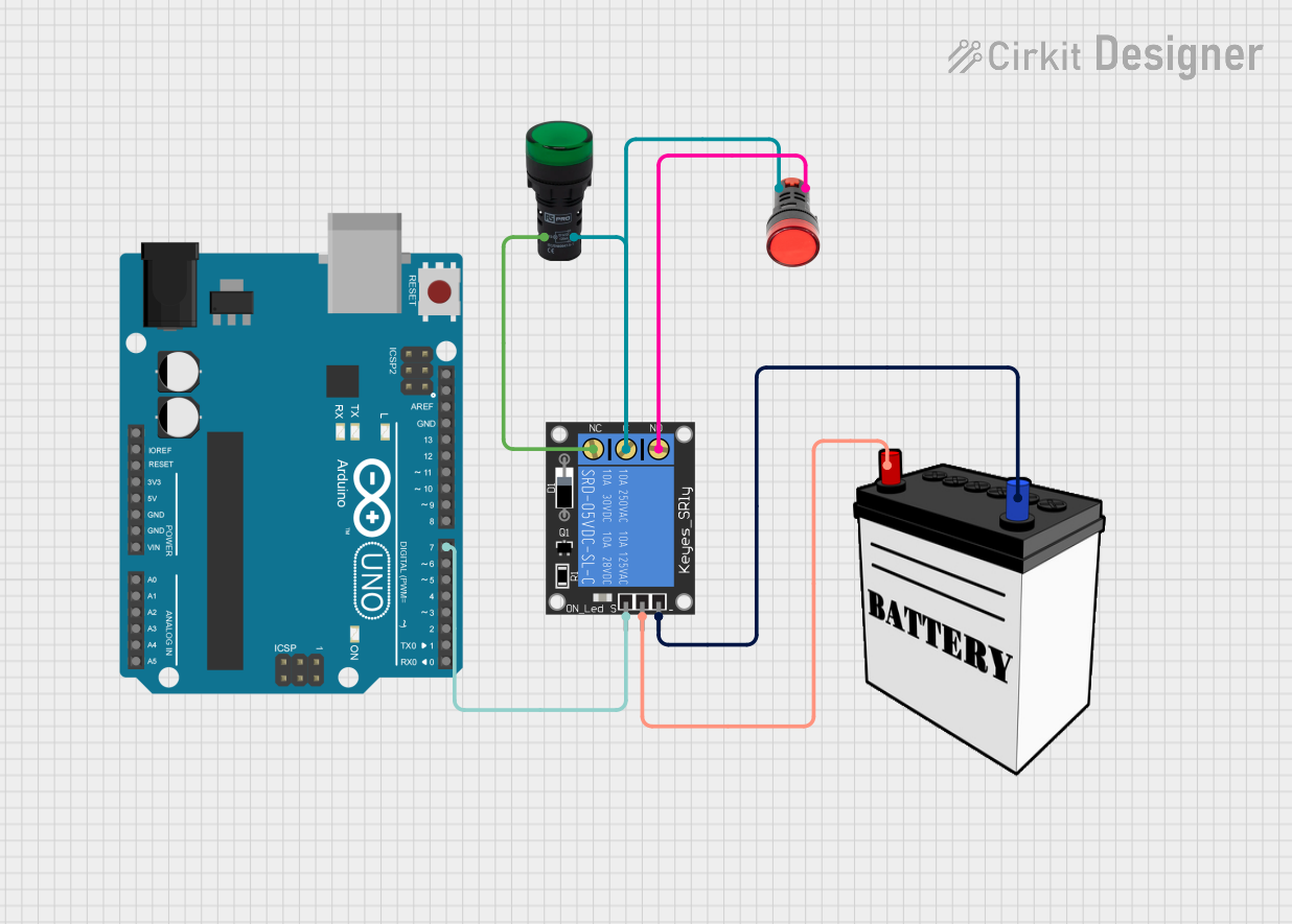
The Pilot Lamp Green is a small indicator lamp that illuminates when electricity flows through it. It is commonly used to visually indicate the operational status of a circuit or device. These lamps are often found on control panels, dashboards, and electronic devices to signal power on, system status, or to alert users to specific conditions.
Explore Projects Built with Pilot Lamp Green
Explore Projects Built with Pilot Lamp Green
Common Applications and Use Cases
- Control panels for machinery
- Power status indicators on electronic devices
- Fault indicators in diagnostic systems
- User interfaces for consumer appliances
Technical Specifications
Key Technical Details
- Voltage Rating: Typically 110V or 220V AC (check specific model)
- Current Rating: Varies with model and voltage (e.g., 20mA at 220V AC)
- Power Consumption: Low, often less than 2W
- Luminous Color: Green
- Lamp Life: Dependent on model, can exceed 20,000 hours
- Operating Temperature: -10°C to +60°C (14°F to 140°F)
Pin Configuration and Descriptions
| Pin Number | Description |
|---|---|
| 1 | Live (Phase) Input |
| 2 | Neutral Return |
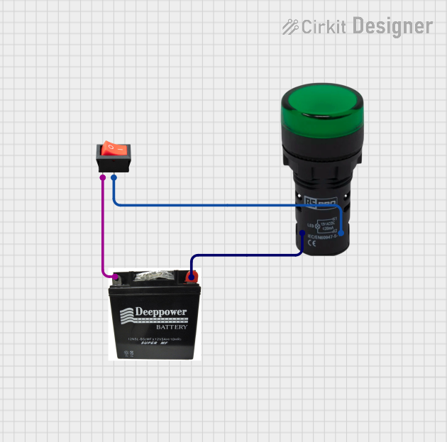
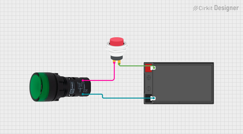
Usage Instructions
How to Use the Pilot Lamp Green in a Circuit
- Identify the Voltage Rating: Ensure the lamp matches the circuit's voltage.
- Connect the Live Wire: Attach the live wire (phase) to pin 1 of the lamp.
- Connect the Neutral Wire: Attach the neutral wire to pin 2 of the lamp.
- Secure Connections: Ensure all connections are secure and insulated.
- Test the Lamp: Power the circuit to test if the lamp illuminates.
Important Considerations and Best Practices
- Voltage Match: Always use a lamp with a voltage rating appropriate for your circuit.
- Heat Dissipation: Ensure the lamp has adequate ventilation as it may generate heat.
- Mounting: Use appropriate fixtures to mount the lamp securely.
- Insulation: Properly insulate all connections to prevent short circuits.
Troubleshooting and FAQs
Common Issues
- Lamp Does Not Illuminate: Check if the lamp is properly connected to the live and neutral wires. Ensure the circuit is powered and the voltage is correct.
- Flickering Lamp: This may indicate a loose connection or fluctuating power supply. Check all connections and the stability of the input voltage.
- Burnt Out Lamp: If the lamp stops working prematurely, it may have been subjected to a voltage higher than its rating or excessive switching cycles.
Solutions and Tips for Troubleshooting
- Check Connections: Verify that all connections are secure and correct.
- Voltage Testing: Use a multimeter to ensure the input voltage matches the lamp's rating.
- Replacement: If the lamp is burnt out, replace it with one of the same voltage and current ratings.
FAQs
Q: Can I use the Pilot Lamp Green with a DC power supply? A: Pilot lamps are typically designed for AC use. Check the manufacturer's specifications for DC compatibility.
Q: Is it necessary to use a resistor with the Pilot Lamp Green? A: No, if the lamp is rated for the circuit's voltage, an additional resistor is not required.
Q: How do I know if the Pilot Lamp Green is compatible with my system? A: Check the voltage and current ratings of the lamp against your system's specifications.
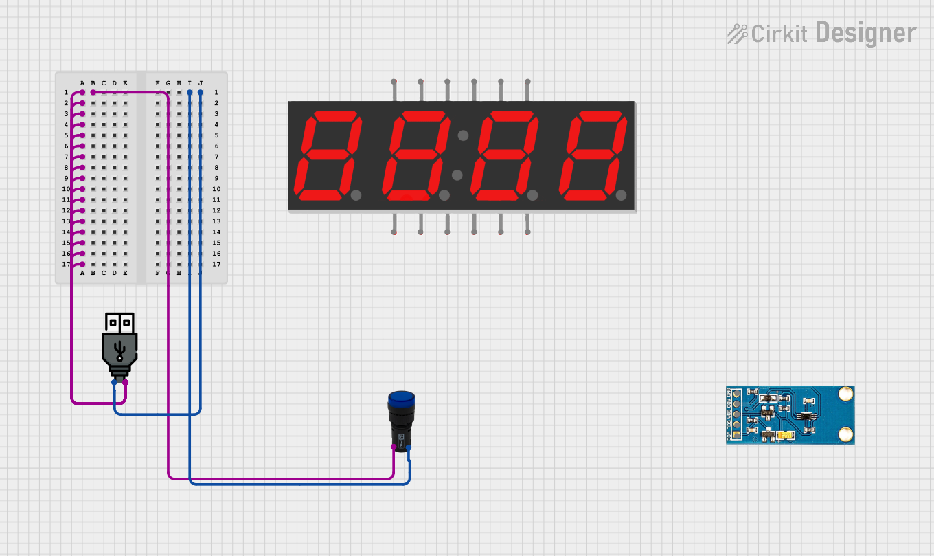
Example Arduino UNO Connection Code
// Define the Arduino pin connected to the lamp
const int pilotLampPin = 13; // Using the onboard LED for demonstration

void setup() {
  pinMode(pilotLampPin, OUTPUT); // Set the pilot lamp pin as an output
}

void loop() {
  digitalWrite(pilotLampPin, HIGH); // Turn on the pilot lamp
  delay(1000);                      // Wait for 1 second
  digitalWrite(pilotLampPin, LOW);  // Turn off the pilot lamp
  delay(1000);                      // Wait for 1 second
}
Note: The above code uses the Arduino's onboard LED as a stand-in for the Pilot Lamp Green. In a real-world application, you would connect the lamp to a digital pin through a relay or transistor that can handle the lamp's AC voltage and current requirements. Ensure proper isolation between the AC circuit and the Arduino's DC control circuitry.