How to Use 25mm Fan 24V: Examples, Pinouts, and Specs
Introduction
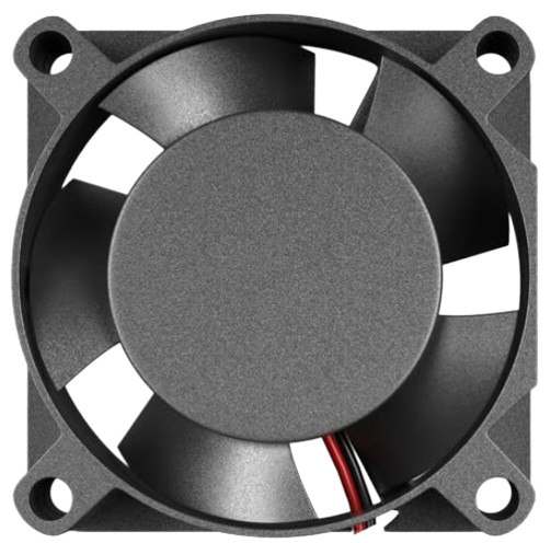
The 25mm Fan 24V is a compact cooling fan designed to operate at 24 volts. It is commonly used for cooling electronic components or small enclosures, ensuring that devices maintain optimal operating temperatures. This fan is ideal for applications where space is limited but efficient cooling is required.
Explore Projects Built with 25mm Fan 24V


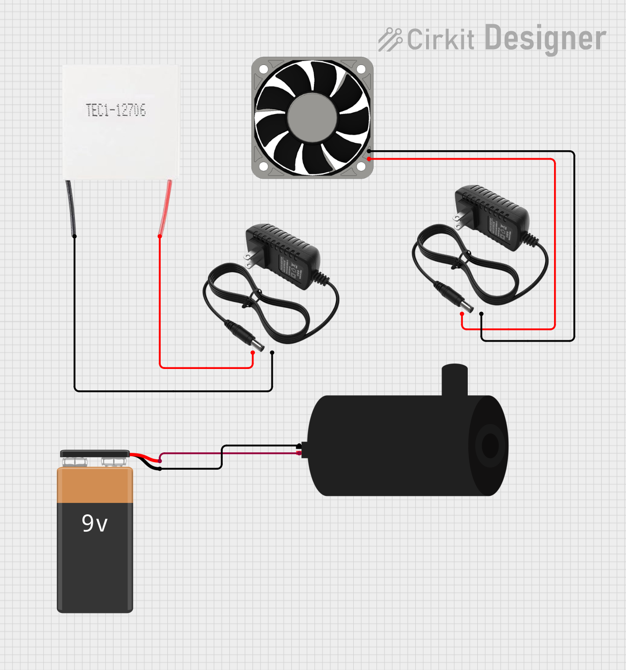

Explore Projects Built with 25mm Fan 24V
Common Applications and Use Cases
- Cooling for 3D printers
- Ventilation for small electronic enclosures
- Heat dissipation for power supplies
- Cooling for computer components
- General-purpose cooling in compact devices
Technical Specifications
Key Technical Details
| Parameter | Value |
|---|---|
| Operating Voltage | 24V DC |
| Current Rating | 0.1A |
| Power Consumption | 2.4W |
| Fan Dimensions | 25mm x 25mm x 10mm |
| Airflow | 5.5 CFM |
| Noise Level | 25 dBA |
| Bearing Type | Sleeve Bearing |
| Connector Type | 2-pin JST |
Pin Configuration and Descriptions
| Pin Number | Pin Name | Description |
|---|---|---|
| 1 | VCC | Positive power supply (24V) |
| 2 | GND | Ground |
Usage Instructions
How to Use the Component in a Circuit
- Power Supply: Ensure you have a stable 24V DC power supply to power the fan.
- Connections:
- Connect the VCC pin of the fan to the positive terminal of the 24V power supply.
- Connect the GND pin of the fan to the ground terminal of the power supply.
- Mounting: Secure the fan in the desired location using screws or adhesive, ensuring that airflow is not obstructed.
Important Considerations and Best Practices
- Voltage: Do not exceed the 24V operating voltage to avoid damaging the fan.
- Orientation: Install the fan in a way that maximizes airflow over the components you wish to cool.
- Noise: Be aware of the noise level (25 dBA) if the fan is used in noise-sensitive environments.
- Maintenance: Periodically clean the fan to prevent dust buildup, which can reduce efficiency and lifespan.
Example: Connecting to an Arduino UNO
While the 25mm Fan 24V operates at a higher voltage than the Arduino UNO can directly supply, you can control the fan using a transistor. Below is an example circuit and code to control the fan using an Arduino UNO and an NPN transistor (e.g., 2N2222).
Circuit Diagram
Components Needed:
- Arduino UNO
- 25mm Fan 24V
- NPN Transistor (e.g., 2N2222)
- 1kΩ Resistor
- Diode (e.g., 1N4007)
- External 24V Power Supply
Connections:
- Connect the emitter of the transistor to GND.
- Connect the collector of the transistor to the GND pin of the fan.
- Connect the VCC pin of the fan to the positive terminal of the 24V power supply.
- Connect the negative terminal of the 24V power supply to the Arduino GND.
- Connect one end of the 1kΩ resistor to Arduino digital pin 9.
- Connect the other end of the 1kΩ resistor to the base of the transistor.
- Place the diode across the fan terminals (cathode to VCC, anode to GND) to protect against back EMF.
Arduino Code
// Define the pin connected to the transistor base
const int fanPin = 9;

void setup() {
  // Set the fan pin as an output
  pinMode(fanPin, OUTPUT);
}

void loop() {
  // Turn the fan on
  digitalWrite(fanPin, HIGH);
  delay(5000); // Keep the fan on for 5 seconds

  // Turn the fan off
  digitalWrite(fanPin, LOW);
  delay(5000); // Keep the fan off for 5 seconds
}
Troubleshooting and FAQs
Common Issues Users Might Face
- Fan Not Spinning:
- Solution: Check the power supply voltage and connections. Ensure the fan is receiving 24V.
- Excessive Noise:
- Solution: Verify that the fan is securely mounted and not obstructed. Clean any dust buildup.
- Fan Stops Intermittently:
- Solution: Check for loose connections or unstable power supply. Ensure the transistor and resistor values are correct if using an Arduino.
Solutions and Tips for Troubleshooting
- Check Connections: Ensure all connections are secure and correct.
- Verify Power Supply: Use a multimeter to check the voltage at the fan terminals.
- Inspect for Obstructions: Make sure there are no physical obstructions preventing the fan blades from spinning.
- Clean the Fan: Regularly clean the fan to prevent dust buildup, which can affect performance.
By following this documentation, users should be able to effectively utilize the 25mm Fan 24V in their projects, ensuring efficient cooling and reliable operation.