How to Use IF Amplifier Eval Board: Examples, Pinouts, and Specs
Introduction
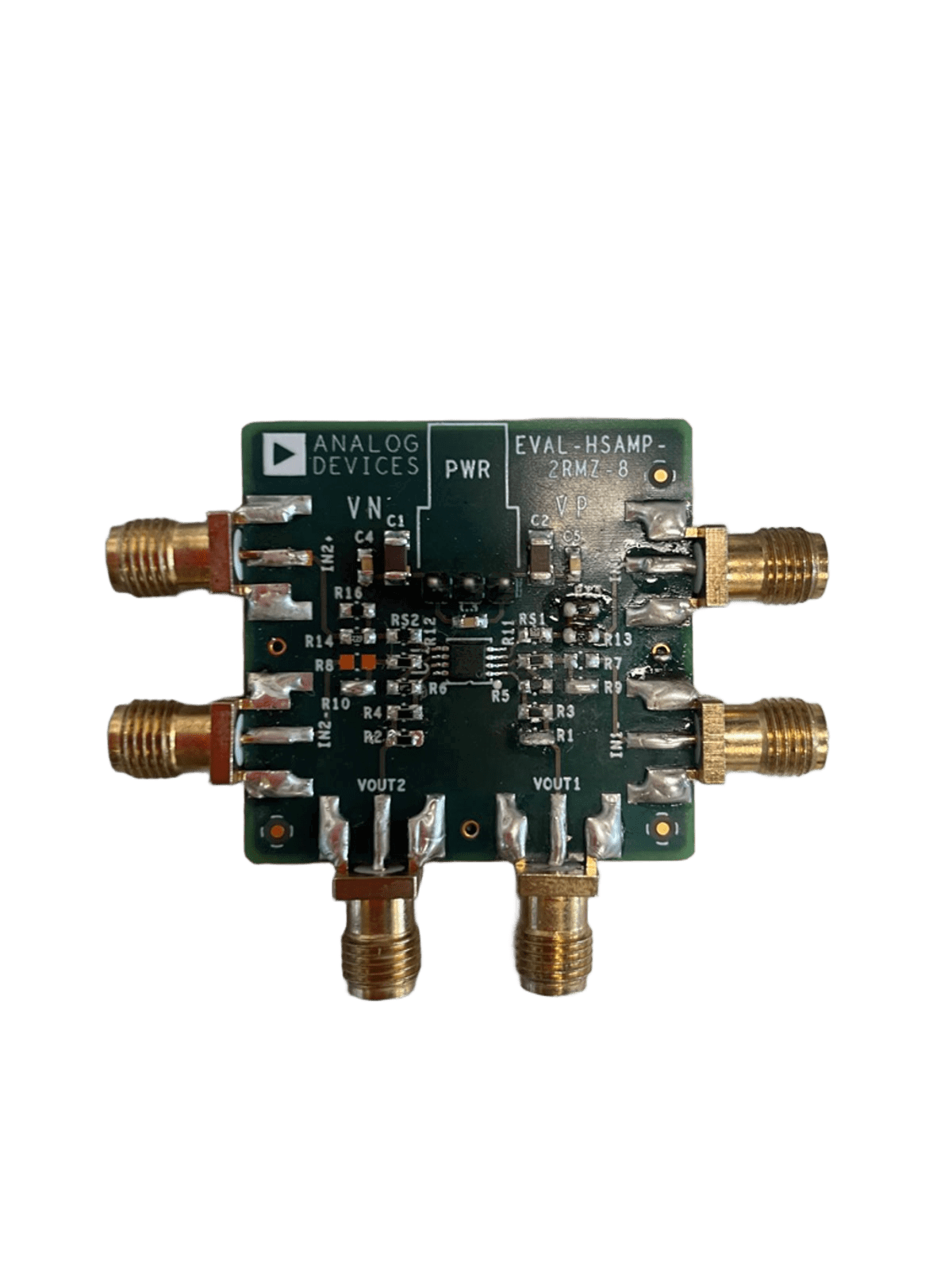
The IF Amplifier Eval Board (EVAL-HSAMP-2RMZ-8), manufactured by Analog Devices, is a development board designed for evaluating intermediate frequency (IF) amplifiers. It provides the necessary circuitry, connectors, and layout to test the performance and functionality of IF amplifiers in a controlled environment. This evaluation board simplifies the process of prototyping and testing, making it an essential tool for RF and analog circuit designers.
Explore Projects Built with IF Amplifier Eval Board
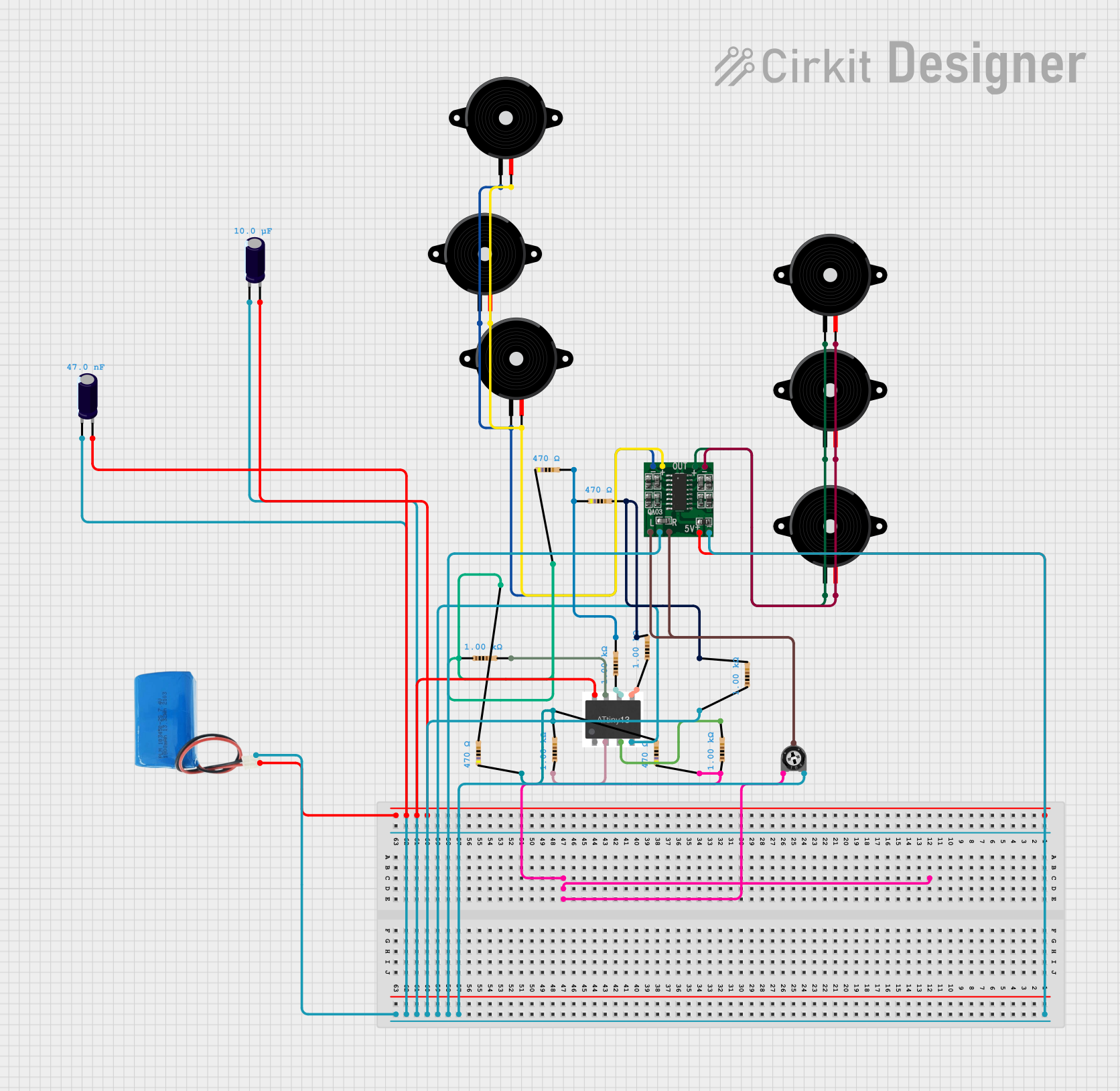

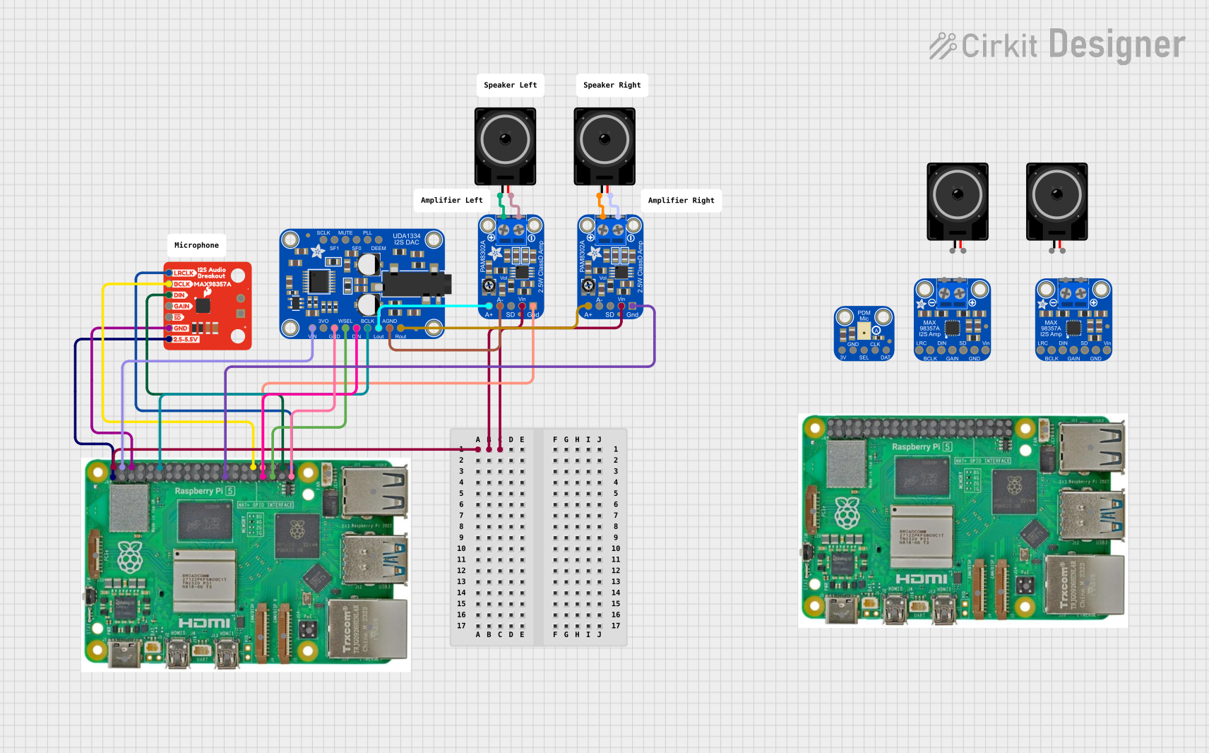
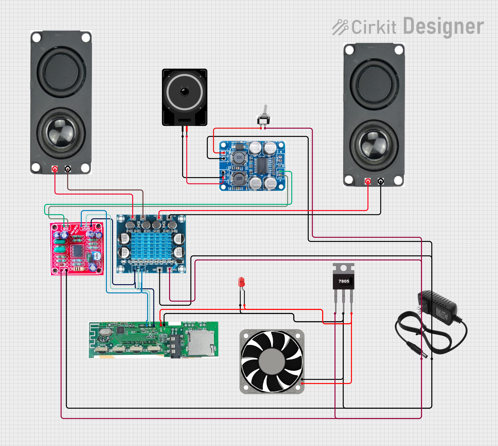
Explore Projects Built with IF Amplifier Eval Board
Common Applications and Use Cases
- Testing and evaluating IF amplifiers in RF communication systems.
- Prototyping and performance validation of IF amplifier circuits.
- Educational purposes for understanding IF amplifier behavior.
- Development of wireless communication systems, radar, and signal processing applications.
Technical Specifications
Key Technical Details
- Manufacturer Part ID: EVAL-HSAMP-2RMZ-8
- Input Frequency Range: 10 MHz to 500 MHz
- Supply Voltage: +5 V DC (typical)
- Input/Output Impedance: 50 Ω
- Gain Range: Dependent on the amplifier under evaluation (refer to the amplifier datasheet).
- Operating Temperature Range: -40°C to +85°C
- Board Dimensions: 50 mm x 50 mm (approximate).
Pin Configuration and Descriptions
The evaluation board includes several key connectors and test points for interfacing with external equipment. Below is a table describing the primary pins and connectors:
| Pin/Connector | Description |
|---|---|
| J1 (Input) | RF input connector for the signal to be amplified. 50 Ω impedance. |
| J2 (Output) | RF output connector for the amplified signal. 50 Ω impedance. |
| VCC | Power supply input (+5 V DC). |
| GND | Ground connection for the power supply and signal reference. |
| TP1, TP2 | Test points for monitoring input and output signals. |
| RFIN, RFOUT | Internal signal paths for connecting the amplifier under evaluation. |
| BIAS | Biasing pin for setting the operating point of the amplifier (if applicable). |
Usage Instructions
How to Use the Component in a Circuit
Power Supply Connection:
- Connect a regulated +5 V DC power supply to the VCC pin and GND pin. Ensure the power supply is capable of providing sufficient current for the amplifier under evaluation.
Signal Input and Output:
- Connect the input signal source (e.g., a signal generator) to the J1 (Input) connector.
- Connect the output signal measurement device (e.g., an oscilloscope or spectrum analyzer) to the J2 (Output) connector.
Amplifier Installation:
- Place the IF amplifier to be evaluated in the designated socket or solder pads on the board. Ensure proper orientation and secure connections.
Biasing and Configuration:
- If the amplifier requires external biasing, use the BIAS pin to set the appropriate operating point. Refer to the amplifier's datasheet for specific biasing requirements.
Testing and Measurement:
- Power on the board and verify the input and output signals using the test points (TP1 and TP2) or external measurement equipment.
- Adjust the input signal frequency and amplitude to evaluate the amplifier's performance across its operating range.
Important Considerations and Best Practices
- Impedance Matching: Ensure that all connected equipment (e.g., signal generator, oscilloscope) has a 50 Ω impedance to avoid signal reflections and losses.
- Thermal Management: If the amplifier under evaluation generates significant heat, consider using a heatsink or active cooling to maintain stable operation.
- Signal Integrity: Use high-quality coaxial cables and connectors to minimize signal degradation.
- Safety: Always power off the board before installing or removing the amplifier to prevent damage to the components.
Example Code for Arduino UNO Integration
While the IF Amplifier Eval Board is not directly designed for microcontroller integration, you can use an Arduino UNO to generate a test signal for the input. Below is an example code snippet to generate a square wave signal using the Arduino's PWM functionality:
// Example: Generate a 1 MHz square wave using Arduino UNO
// Note: The output frequency is limited by the Arduino's clock speed.

void setup() {
  pinMode(9, OUTPUT); // Set pin 9 as output for PWM signal

  // Configure Timer1 for 1 MHz square wave
  TCCR1A = _BV(COM1A0); // Toggle OC1A on Compare Match
  TCCR1B = _BV(WGM12) | _BV(CS10); // CTC mode, no prescaling
  OCR1A = 7; // Set output compare register for 1 MHz frequency
}

void loop() {
  // The square wave is generated automatically by the timer
}
Note: The output signal from the Arduino UNO may require additional filtering or amplification to match the input requirements of the evaluation board.
Troubleshooting and FAQs
Common Issues and Solutions
No Output Signal:
- Verify that the power supply is connected and providing the correct voltage (+5 V DC).
- Check the input signal source and ensure it is functioning correctly.
- Confirm that the amplifier is properly installed and oriented on the board.
Distorted Output Signal:
- Ensure that the input signal amplitude is within the acceptable range for the amplifier.
- Check for impedance mismatches between the board and connected equipment.
- Verify that the amplifier's biasing is correctly configured.
Excessive Heat:
- Ensure proper thermal management for the amplifier under evaluation.
- Reduce the input signal amplitude if the amplifier is operating near its maximum power rating.
FAQs
Q: Can I use a different power supply voltage?
A: No, the board is designed to operate with a +5 V DC supply. Using a different voltage may damage the components.
Q: What is the maximum input signal level?
A: The maximum input signal level depends on the specific amplifier being evaluated. Refer to the amplifier's datasheet for details.
Q: Can I use this board for frequencies outside the 10 MHz to 500 MHz range?
A: The board is optimized for the specified frequency range. Performance outside this range may degrade significantly.
This documentation provides a comprehensive guide to using the EVAL-HSAMP-2RMZ-8 IF Amplifier Eval Board. For further details, refer to the official datasheet and application notes provided by Analog Devices.