How to Use GND Rail: Examples, Pinouts, and Specs
Introduction
A GND rail is a critical component in electronic circuits, serving as a common reference point for all ground connections. It ensures a stable voltage reference across the circuit and helps reduce electrical noise, which is essential for reliable operation. GND rails are typically implemented as conductive traces on a PCB (Printed Circuit Board) or as a physical bus bar in larger systems.
Explore Projects Built with GND Rail

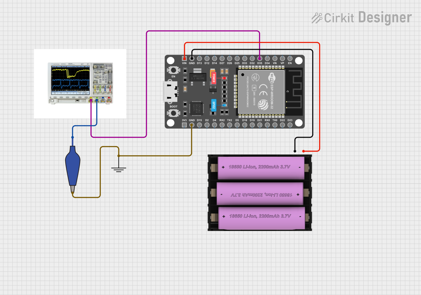
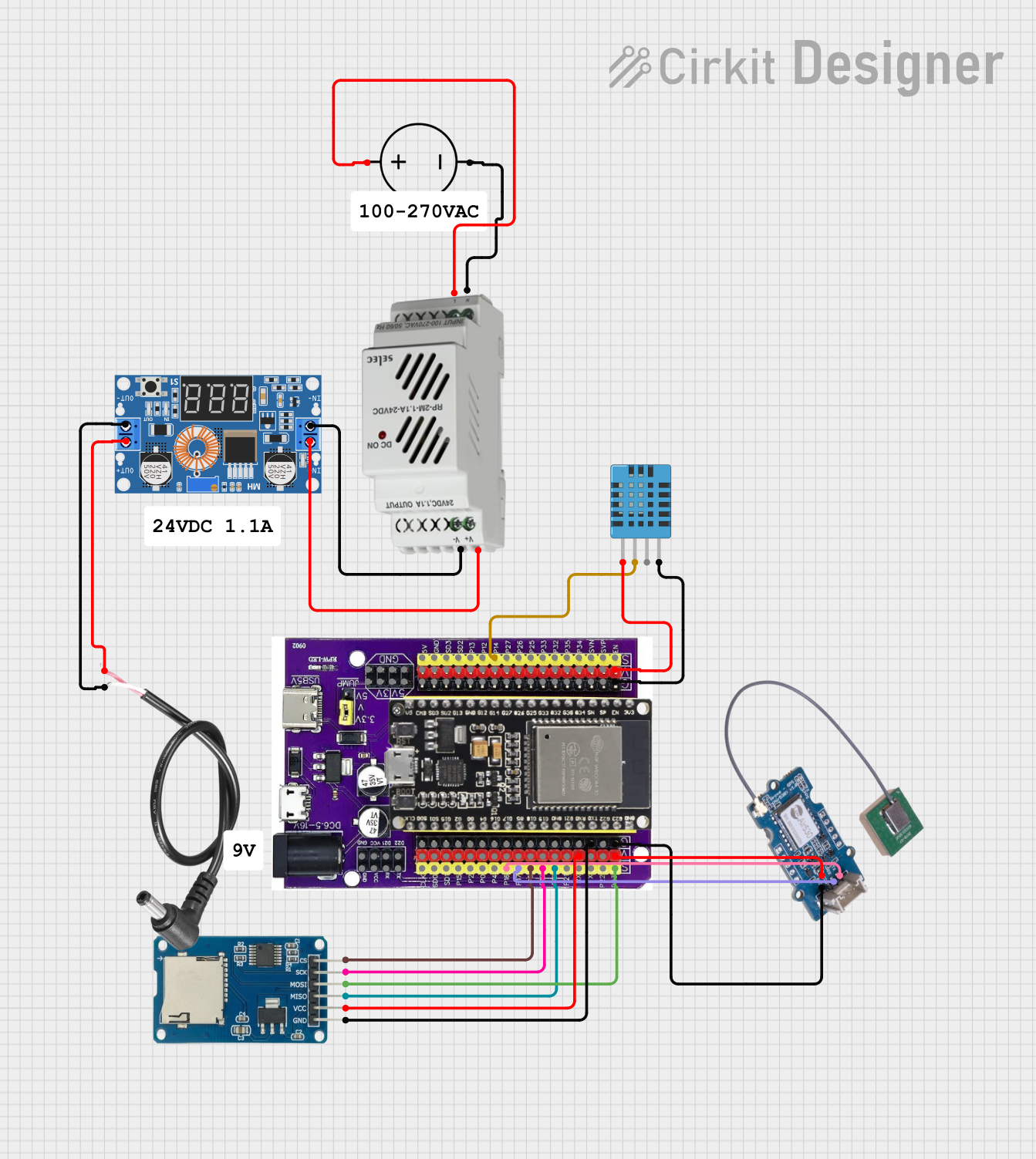

Explore Projects Built with GND Rail
Common Applications and Use Cases
- Power Distribution: Provides a shared ground reference for power supplies and components.
- Signal Integrity: Reduces noise and interference in analog and digital signals.
- Circuit Debugging: Acts as a reference point for voltage measurements.
- PCB Design: Used in multi-layer boards to create a dedicated ground plane.
Technical Specifications
While a GND rail itself does not have specific electrical ratings, its implementation depends on the circuit's requirements. Below are general considerations for designing or using a GND rail:
Key Technical Details
- Voltage Reference: 0V (ground potential).
- Current Capacity: Depends on the width and thickness of the trace or conductor.
- Material: Typically copper for PCB traces or aluminum/copper for bus bars.
- Impedance: Should be as low as possible to minimize voltage drops and noise.
Example Pin Configuration (for a PCB GND Rail)
| Pin/Connection | Description |
|---|---|
| GND | Common ground connection for all devices |
| VCC | Positive voltage supply (not part of GND rail but often paired) |
Usage Instructions
How to Use the GND Rail in a Circuit
Designing the GND Rail:
- On a PCB, use a wide trace or a dedicated ground plane to minimize resistance.
- Ensure all components requiring a ground connection are tied to the GND rail.
- For high-current circuits, consider using thicker traces or external bus bars.
Connecting Components:
- Connect the negative terminal of power supplies to the GND rail.
- Tie the ground pins of ICs, sensors, and other components to the GND rail.
- Use decoupling capacitors between the GND rail and power supply lines to filter noise.
Best Practices:
- Avoid creating ground loops, which can introduce noise.
- Use a star grounding topology for sensitive analog circuits.
- For multi-layer PCBs, dedicate one layer as a ground plane for better performance.
Example: Using a GND Rail with an Arduino UNO
When connecting an Arduino UNO to external components, the GND rail ensures all devices share a common ground reference.
Circuit Diagram
- Connect the GND pin of the Arduino UNO to the GND rail.
- Tie all other components' ground connections to the same rail.
Sample Code
// Example: Reading a sensor value with a shared GND rail

const int sensorPin = A0; // Analog pin connected to the sensor output
int sensorValue = 0;      // Variable to store the sensor reading

void setup() {
  Serial.begin(9600); // Initialize serial communication
}

void loop() {
  sensorValue = analogRead(sensorPin); // Read the sensor value
  Serial.print("Sensor Value: ");
  Serial.println(sensorValue); // Print the sensor value to the Serial Monitor
  delay(500); // Wait for 500ms before the next reading
}
Note: Ensure the sensor's ground pin is connected to the GND rail for accurate readings.
Troubleshooting and FAQs
Common Issues
Voltage Drops Across the GND Rail:
- Cause: High resistance in the GND rail due to narrow traces or poor connections.
- Solution: Use wider traces or a dedicated ground plane. For high-current circuits, use thicker wires or bus bars.
Ground Loops:
- Cause: Multiple ground paths create loops, introducing noise.
- Solution: Use a single-point ground (star grounding) or isolate ground connections.
Noise in Signals:
- Cause: Poor grounding or lack of decoupling capacitors.
- Solution: Add decoupling capacitors near power pins and ensure a low-impedance GND rail.
FAQs
Q: Can I use a single GND rail for both analog and digital circuits?
A: While it's possible, it's better to separate analog and digital grounds to reduce noise. Connect them at a single point if necessary.
Q: How wide should a PCB GND trace be?
A: The width depends on the current it needs to carry. Use PCB trace width calculators to determine the appropriate size based on current and copper thickness.
Q: What happens if the GND rail is disconnected?
A: Components will lose their reference voltage, leading to erratic behavior or failure. Always ensure a solid ground connection.
By following these guidelines, you can effectively implement and troubleshoot a GND rail in your electronic projects.